Lab 1 - Intro to DC Circuits
ECE209 - Fundamentals of Electrical Engineering
Electrical and Computer Engineering - University of Alberta
1 Objectives
The first lab session will have the students familiarize themselves with some common electrical tools and components used for circuits and use them to experimentally test and confirm the validity of concepts learned in the lectures. The objectives for this lab are therefore to:
Familiarize yourself with a common benchtop DC Power Supply and all of of its functions.
Familiarize yourself with the use of a Digital Multimeter to appropriately measure resistance, DC voltage and DC current.
Use the Resistors on the Student Printed Circuit Board to investigate Ohm’s Law, Power Dissipated in a Resistor and Kirchoffs Laws.
Setup a circuit that demonstrates that a voltmeter can have a significant loading effect on a circuit.
These objectives should be kept in mind as the students work through the lab procedure.
2 Pre-Lab
Before attending the lab, please complete the following:
Note:
Labs are typically completed in groups of two, so please try to pair up before coming to the lab. Each student needs to complete the pre-lab and hand it in at the start of their scheduled lab session. Only one lab report is required to be handed-in per group which is due one week after the schedule lab session. If you can’t find a partner we will either pair you up in the lab or you may also be permitted to work by yourself if there is an available station.
Completely read through the information discussed in the Background section below and please skim through this lab manual to become familiar with what will be required of you during the lab.
Familiarize yourself with the Equipment used in the first lab by going though the pages for each piece of equipment in the Equipment List.
Make sure you have either an electronic device with you where you can access this lab manual or print out the Lab 1 - Manual before coming to your lab section.
Make sure you print out a Lab 1 - Results Sheet to record all of your results. You only require one printout per group.
Complete the following on the Lab 1 - Results Sheet before coming to the lab. Everything in light green on the results sheet is part of the prelab.
For the resistors in table 1. RESISTORS A - (4-band resistors) and table 2. RESISTORS B - (5-band resistors) determine the color code and tolerance for each resistor. Using the tolerance, calculate both the possible low value and high value that the actual resistance of that resistor should fall between.
For the table 3. Series Resistors and table 4. Parallel Resistors calculate the effective resistance of those two resistors when placed in the corresponding configuration.
For the Current Divider circuit in figure 10 calculate the total effective resistance that is seen by the supply for each setting of R2. Also calculate the supply current (IS) and the currents through each branch IR1 and IR2 for each setting of R2.
For the Voltage Divider circuit in figure 12 calculate the total effective resistance that is seen by the supply for each setting of R2. Also calculate the supply current (IS) and the voltages across each resistor VR1 and VR2 for each setting of R2.
For the Loading Effect circuit in figure 15 calculate the voltage drop across both R1 and R2 assuming no voltmeter is connected.
Complete these Pre-lab Questions on a seperate piece of paper to hand in at the beginning of your lab session. Make sure to include an appropriate title, your first and last name, CCID, student ID and your lab section at the top of the page.
The Digital Multimeter (DMM) used in the lab is the Fluke 175. This multimeter, like most have four input terminals on the front of the device. In your own words describe what each of these four input terminals are generally used for.
The DC Power Supply used in the lab is the BK Precision 1651A. This power supply has three independent supplies all in the same unit. List some of the features of each supply including its voltage and current ratings.
Resistors typically have two important ratings: its resistance and its wattage. All of the resistors on the Student Printed Circuit Board are rated at 1/4 Watt. Using a few example calculations explain how this wattage rating effects the amount of voltage that can be applied to different resistor values.
2.1 Background
2.2 Equipment List
3 Procedure
3.1 Equipment Familiarization
3.1.1 Student PC Board

figure 1. Student Printed Circuit Board
Look at the Student Printed Circuit Board used for this lab and notice the different sections. Today we will only be using the sections labeled RESISTORS A and RESISTORS B.
RESISTORS A - Is made up of 4-band 1/4 watt resistors of various values which are connected to a banana jacks on either end.
RESISTORS B - Is made up of 5-band 1/4 watt resistors of various values which are connected to a banana jacks on either end but one side of all of the resistors is connected to a common point.
RESISTORS C - Has 4 smaller resistance 5-band 1/4 watt resistors which are connected to a banana jacks on either end and typically used for current sensing.
DIODE BRIDGE - Is made up of 4 rectifier diodes connected to banana jacks that are connected in a bridge configuration for the purpose of converting an AC voltage to a DC voltage. This is not used in this course.
OP-AMP - Is an common operational amplifier which can be connected to banana plugs. This is also not used in this course.
2m5H INDUCTOR - A 2.5mH inductor which can be connected to a banana plugs. It will be used in later in this course once you get into AC circuits.
CAPACITORS - Is made up of 4 different capacitors connected to a banana jacks. they will also be used in later in this course once you get into AC circuits.
3.1.2 DC Power Supply

figure 2. BK Precision DC Power Supply (1651A)
Adjustable DC Voltage Source
Use the power supply as an adjustable DC voltage source and note the following features.
Turn the power supply on using the power switch.
Select the independant mode using the parallel/series/independant switch.
Select channel A using the A/B switch to use the voltmeter and ammeter needle displays to monitor the voltage and current output for channel A.
Both channel A and B have knobs to adjust the set-points for voltage and current. Make sure the current knob for channel A is not zero. Adjust the voltage knob for channel A and notice the needle movement on the voltmeter shows the output voltage for channel A.
Note:
If you adjust the current knob to zero notice that the voltage also goes to zero. When this happens you will also notice a red light come on above the output terminals.Switch the A/B switch to channel B and notice that the voltage and current control knobs for channel B now operate in a similar fashion as channel A.
Note:
If the power supply is on all channels will always be active, the A/B switch only changes which channel is displayed on the volt and am-meters.There is also a separate 5 volt fixed power supply that can supply up to 4 amps.
Adjustable DC Current Source
Use the power supply as an adjustable DC current source and note the following features.
Turn the power supply off and use a banana lead to short the red positive terminal to the black negative terminal of the channel A output terminals.
Select independant mode and channel A metering.
Turn the power supply back on.
Make sure the voltage knob for channel A is not zero. Adjust the current knob for channel A and notice the needle movement on the ammeter shows the output current for channel A.
Note:
The red light above channel A’s output terminals is on when the power supply is in current control mode and off when the power supply is in voltage control mode. Therefore the current knob will only control the output current when the red light is on and the voltage knob will only control the output voltage when the red light is off. Which control mode is active will depend on which set-point the output reaches first: the voltage or the current.Channel B operates the same as channel A.
Turn off the power supply.
Note:
Not all power supplies have current limit/control capability and shorting the terminals like this on a piece of equipment that does not can destroy that piece of equipment due to large currents.
3.1.3 Digital Multimeter

figure 3. Fluke Multimeter (175)
3.1.3.1 Measure Resistance
Prepare the digital multimeter (DMM) to measure a resistance.
Turn the large dial on the multimeter to select resistance measurement
Ω.Connect a red banana lead to the
Ωinput near the bottom of the device.Connect a black banana lead to the
COMinput of the device.When nothing is connected to the banana leads it should display
OLindicating an open circuit.When you short the red and black banana leads together it should display approximately
0.0indicating a short circuit.
4-band Resistors
- Use the multimeter to measure the 4-band resistors from RESISTORS A on the PC Board from the table below and record your measurements in the appropriate place on the results sheet.
| R1 | R2 | R3 | R4 |
|---|---|---|---|
| 1.8k | 4.7k | 62k | 4.7M |
5-band Resistors
- Use the multimeter to measure the 5-band resistors from RESISTORS B on the PC Board from the table below and record your measurements in the appropriate place on the results sheet.
| R5 | R6 | R7 | R8 |
|---|---|---|---|
| 1.00k | 20.0k | 40.2k | 200k |
Series Resistors
- Place the following resistors in series and then use the multimeter to measure the total resistance across the resistors and record your measurements in the appropriate place on the results sheet.
| RS1 | RS2 | RS3 | RS4 |
|---|---|---|---|
| 1.8k + 4.7k | 4.99k + 40.2k | 20.0k + 200k | 5.6k + 10.0k + 20.0k |
Parallel Resistors
- Place the following resistors in parallel and then use the multimeter to measure the total resistance across the resistors and record your measurements in the appropriate place on the results sheet.
| RP1 | RP2 | RP3 | RP4 |
|---|---|---|---|
| 1.8k // 4.7k | 4.99k // 40.2k | 20.0k // 200k | 5.6k // 10.0k // 20.0k |
3.1.3.2 Measure DC Voltage
Note:
An ideal voltmeter is an open circuit.
Use the multimeter to measure a DC voltage.
Turn the large dial on the multimeter to select DC Voltage measurement
V.Connect a red banana lead to the
Vinput and black banana lead to theCOMinput near the bottom of the multimeter.When nothing is connected to the multimeter it should display
0.000V DC.Connect the other end of the red and black banana leads to the red
+and black-terminals of channel A of the power supply.Turn on the power supply and verify that both independant and channel A are selected.
Use the voltage control knob for channel A to change the voltage and show that the voltage on the meter on the power supply is approximately the same as the display on the multimeter.
Use the needle display on the power supply to adjust the DC voltage to the following settings as close as possible; Then use the multimeter to record the corresponding measurements in the appropriate place on the results sheet.
Note: Make sure you are viewing the meter displays on the power supply directly from in front as viewing angle will effect measurement accuracy.
table 5. DC voltage measurements - needle position V1 V2 V3 5V 10V 20V Turn off the power supply.
Disconnect the meter from the power supply.
3.1.3.3 Measure DC Current
Note:
An ideal ammeter is a short circuit.
Use the multimeter to measure a DC current.
Turn the large dial on the multimeter to select the (mA) measurement and press the yellow button to cycle between AC, DC and Hz. Cycle until you have the DC measurement selected.
Warning:
If you select the AC or Hz selection by mistake when trying to measure a DC quantity the meter will always read zero even if you apply a DC voltage.Connect a red banana lead to the
400mAinput and black banana lead to theCOMinput near the bottom of the multimeter.Warning:
Do not exceed 400mA using these inputs as exceeding that current will blow the internal fuse. If a larger current measurement is desired connect the red banana lead to the10Ainput at the buttom of the multimeter instead and use the corresponding large dial selection.When nothing is connected to the multimeter it should display ~
0.00mA DC.Connect the other end of the red and black banana leads to the red
+and black-terminals of channel A of the power supply.Warning:
The power supply can output a maximum of 500mA when the current control knob is turned fully clockwise. As stated above the digital multimeter can only take a maximum of 400mA when on this input before the internal fuse will blow. Therefore, start with the current control knobs fully counter-clockwise and do not exceed the half way mark unless you are sure the output current is safely below 400mA.Turn on the power supply and verify that both independant and channel A are selected.
Use the current control knob for channel A to change the current and show that the current on the meter on the power supply is approximately the same as the display on the multimeter.
Use the needle display on the power supply to adjust the DC current to the following settings as close as possible; Then use the multimeter to record the corresponding measurements in the appropriate place on the results sheet.
Note:
Make sure you are viewing the needle meter displays on the power supply directly from in front as viewing angle will effect measurement accuracy.
table 6. DC current measurements - needle position I1 I2 I3 100mA 200mA 300mA - Disconnect the meter from the power supply.
3.1.4 Power Supply Cont…
3.1.4.1 Series Mode
Series Mode
Puts the channel A supply in series with channel B supply for the purpose of doubling the available voltage.
Use the two channels A and B of the power supply in series mode.
Select the series mode using the series/parallel/independant switch on the power supply.
Note:
When series mode is selected the red terminal of channel B is internally connected to the black terminal of channel A so no external connection is required. Also when in this mode, only the channel A controls are used which controls both of channel A and B to the same value. Also note that the voltmeter on the power supply will only show either the channel A voltage or the channel B voltage but not the sum.Setup the multimeter to measure the DC output voltage of the power supply as shown below.
Warning:
Remember to move the banana leads to the appropriate inputs of the multimeter and set the multimeter dial accordingly.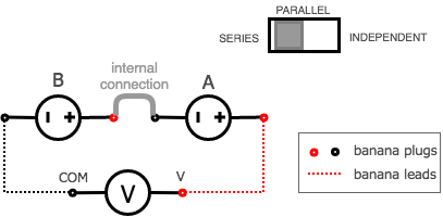
figure 4. DC Power Supplies Connected in Series)
Use the needle display on the power supply to adjust the DC voltage to the following settings as close as possible; Then use the multimeter to record the corresponding measurements in the appropriate place on the results sheet.
table 7. series power supplies - needle position V1 V2 V3 5V 10V 20V - Turn off the power supply
3.1.4.2 Parallel Mode
Parallel Mode
Puts the channel A supply in parallel with channel B supply for the purpose of doubling the available current.
Use the two channels of the power supply in parallel mode.
Select the parallel mode using the series/parallel/independant switch on the power supply.
Note:
When parallel mode is selected the red terminals of channel A and B is internally connected, same with the black terminals, so no external connection is required. Also when in this mode, only the channel A controls are used which controls both of channel A and B to the same value. Also note that the ammeter on the power supply will only show either the channel A current or the channel B current but not the sum.Setup the multimeter to measure the DC output current of the power supply as shown below. Use the 10A inputs on the multimeter and appropriate dial setting making sure to use the yellow button to enable the DC measurement.
Warning:
Use the 10A current inputs and settings on the multimeter as the current of the power supply can now significantly exceed the 400mA capability of the other input.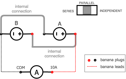
figure 5. DC Power Supplies Connected in Parallel)
Use the needle display on the power supply to adjust the DC current to the following settings as close as possible; Then use the multimeter to record the corresponding measurements in the appropriate place on the results sheet.
table 8. parallel power supplies - needle position A1 A2 A3 100mA 200mA 400mA - Remove the multimeter and place the power supply back into independent mode and turn it off.
3.1.5 Decade Box

figure 6. Ohmite Decade Box (Determ-ohm)
- Measure the resistance of the decade resistance box using the multimeter at the following settings and record your measurements in the appropriate place on the results sheet.
| RD1 | RD2 | RD3 | RD4 |
|---|---|---|---|
| 1k | 5k | 12k | 38k |
3.2 Ohms Law and Power Dissipation
Ohm’s Law
The resistor’s current IR in amps (A) is equal to the resistor’s voltage VR in volts (V) divided by the resistance R in ohms (Ω):
\[I_R = \frac{V_R}{R} \quad \text{or} \quad V_R = I_R \cdot R \quad \text{or} \quad R = \frac{V_R}{I_R}\]
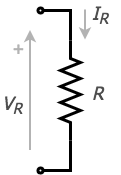
figure 7. A Resistor
Power Dissipated in Resistors
Any resistor in a circuit that has a voltage drop across it dissipates electrical power. This electrical power is converted into heat energy hence > all resistors have a power rating. This is the maximum power that can be dissipated from the resistor without it burning out. The rate of conversion is the power of dissipation.
\[P = {I_R}\cdot{V_R} \quad \text{or} \quad P = I_R^2 \cdot R \quad \text{or} \quad P = \frac{V_R^2}{R}\]
Use the Ohm’s Law Test Circuit to compare a resistors stated value with the calculated value from Ohm’s Law using its measured current and voltage at different operating points. The power dissipated by the resistor at each point can also be calculated. Complete the procedure for three different resistor values.
- Connect the circuit in figure 1 using the following:
- 1.8k resistor from the Student PC board.
- The multimeter as a milliammeter.
- Channel A as a voltage source from the DC power supply.
- The appropriate banana leads.
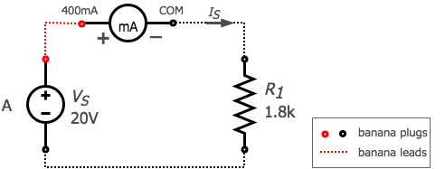
figure 8. Ohm’s Law Test Circuit
- Use the multimeter to measure the current and the needle voltmeter display on the DC power supply to measure the voltage at each voltage setpoint below and record your result in the appropriate place on the results sheet.
table 10. six voltage testpoints V1 V2 V3 V4 V5 V6 20 V 10 V 5 V -5 V -10 V -20 V Note:
To apply a negative DC voltage across the resistor interchange the red and black banana plugs at the output terminals of the power supply. Replace the 1.8k resistor with a 4.7k resistor and make the same measurements again while recording your results in the appropriate place in the results sheet.
Replace the resistor again with a 20.0k resistor and make the same measurements again while recording your results in the appropriate place in the results sheet.
Turn off the power supply and disconnect the circuit.
- Connect the circuit in figure 1 using the following:
3.3 Current Divider
Kirchoffs Current Law
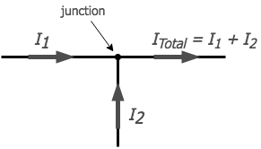
figure 9. Kirchoffs Current Law
Kirchhoff’s Current Law (KCL) is one of the fundamental laws used for circuit analysis. His current law states that for a parallel path the total current entering a circuits junction is exactly equal to the total current leaving the same junction. This is because it has no other place to go as no charge is lost.
In other words the algebraic sum of ALL the currents entering and leaving a junction must be equal to zero as: \(\Sigma I_{IN} = \Sigma I_{OUT}\).
This idea by Kirchhoff is commonly known as the Conservation of Charge, as the current is conserved around the junction with no loss of current.
Use the Parallel Resistor Test Circuit to demonstrate that the supply current divides into both resistors according to Kirchoffs Current Law (KCL). You will be changing the value of one of the resistors to show how the change effects the circuit current flow and power dissipation.
Set the Decade Box to a resistance of 450Ω.
Use the multimeter as a voltmeter to set channel A of the DC power supply to 15V. Turn the DC power supply off before proceeding to the next step.
- Connect the circuit in figure 10 using the following:
- Use the DC power supply as a DC source.
- The multimeter as a milliammeter.
- 1.8k resistor from the Student PC Board for R1.
- The Decade Box for R2.
- The appropriate banana leads.
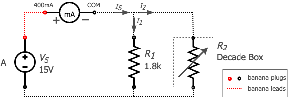
figure 10. Parallel Resistor Test Circuit
- Turn the DC power supply back on and measure the supply current for each of the values of R2 in the table below. Record each one in the appropriate place on the results sheet.
table 11. R2 in parallel setpoints - decade box R2_1 R2_2 R2_3 R2_4 R2_5 R2_6 450 900 1.8k 3.6k 7.2k 14.4k Note:
Reducing the Decade Box Resistance below a certain value will cause the DC power supply to go into current control mode. Turn the DC power supply off and move the multimeter in the circuit so I1 can now be measured.
Turn the DC power supply back on and repeat the value’s of R2 with the milliammeter in its new position and record each reading in the appropriate place on the results sheet.
Turn the DC power supply off and move the multimeter in the circuit so I2 can now be measured.
Turn the DC power supply back on and repeat the value’s of R2 with the milliammeter in its new position and record each reading in the appropriate place on the results sheet.
Turn the DC power supply off and disconnect the circuit.
3.4 Voltage Divider
Kirchoffs Voltage Law
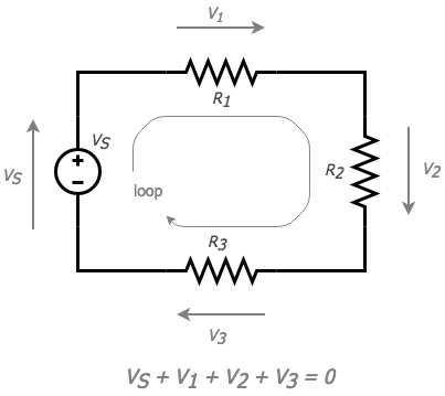
figure 11. Kirchoffs Voltage Law
Kirchhoff’s Voltage Law (KVL) is the second of his fundamental laws we can use for circuit analysis. His voltage Law states that for a closed loop series path the algebraic sum of all the voltages around any closed loop in a circuit is equal to zero. This is because a circuit loop is a closed conducting path so no energy is lost.
In other words the algebraic sum of ALL the potential differences around the loop must be equal to zero as: \(\Sigma V = 0\). Note here that the term “algebraic sum” means to take into account the polarities and signs of the sources and voltage drops around the loop.
This idea by Kirchhoff is commonly known as the Conservation of Energy, as moving around a closed loop, or circuit, you will end up back to where you started in the circuit and therefore back to the same initial potential with no loss of voltage around the loop. Hence any voltage drops around the loop must be equal to any voltage sources met along the way.
For this test you will use the power supply to apply a voltage across two resistors in series while measuring both the current and the voltage across each of the resistors. This is to demonstrate that the voltage across the resistors divides according to Kirchoffs Voltage Law (KVL). You will be changing the value of one of the resistors to demonstrate how the voltage across the resistors changes.
Set the Decade Box to a resistance of 450Ω.
Use the multimeter as a voltmeter to set channel A of the DC power supply to 15V. Turn the DC power supply off before proceeding to the next step.
- Connect the circuit in figure 12 using the following:
- Use the DC power supply as a DC source.
- The multimeter as a milliammeter.
- 1.8k resistor from the Student PC Board for R1.
- The Decade Box for R2.
- The appropriate banana leads.
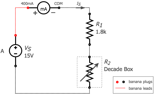
figure 12. Series Resistor Test Circuit
- Turn the DC power supply back on and measure the supply current for each of the values of R2 in the table below. Record each one in the appropriate place on the results sheet.
table 12. R2 in series setpoints - decade box R2_1 R2_2 R2_3 R2_4 R2_5 R2_6 450 900 1.8k 3.6k 7.2k 14.4k Turn the DC power supply off and remove the multimeter from the circuit making sure to replace the milliammeter with a short circuit. Setup the multimeter as a DC voltmeter so the voltage across R1 can now be measured.
Turn the DC power supply back on and repeat the value’s of R2 with the multimeter in its new position and record each reading in the appropriate place on the results sheet.
Turn the DC power supply off and move the multimeter in the circuit so the voltage across R2 can now be measured.
Turn the DC power supply back on and repeat the value’s of R2 with the multimeter in its new position and record each reading in the appropriate place on the results sheet.
Turn the DC power supply off and disconnect the circuit.
3.5 Loading Effect
Non-ideal Voltmeter
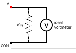
figure 13. Non-ideal Voltmeter
An ideal voltmeter imposes no load on the circuit being measured so as to not disturb the circuit. In practice, voltmeters draw some current and hence some small amount of load to the circuit affecting results.
So in an ideal voltmeter, the resistance of the meter is infinite.
In practice, voltmeters originally had resistance of several thousand ohms, 30KΩ or 100KΩ was common. The resulting power used was required to deflect a moving needle galvanometer type meter.
Later electronic meters with input amplifiers such as your Vacuum tube and transistorized volt meters drew much less current with very high impedance and active amplifiers to drive the meter movements; today’s digital multimeters are typically set at 10,000,000 Ω.
Non-ideal Ammeter
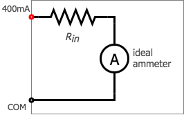
figure 14. Non-ideal Ammeter
Just like voltmeters, ammeters tend to influence the amount of current in the circuits they’re connected to. However, unlike the ideal voltmeter, the ideal ammeter has zero internal resistance, so as to drop as little voltage as possible as electrons flow through it. Note that this ideal resistance value is exactly opposite as that of a voltmeter. With voltmeters, we want as little current to be drawn as possible from the circuit under test. With ammeters, we want as little voltage to be dropped as possible while conducting current.
Use the Non-ideal Voltmeter Test Circuit to demonstrate that a practical voltmeter can give you large errors in your measurements if you are not careful due to the loading effect.
Use the multimeter as a voltmeter to set channel A of the DC power supply to 11.5V. Turn the DC power supply off before proceeding to the next step.
- Connect the Circuit in the figure below using the following.
- Use the DC power supply as a DC source.
- The multimeter as a voltmeter.
- The 4.7M and 6.8M resistors from the Student PC Board for R1 and R2 respectively.
- The appropriate banana leads
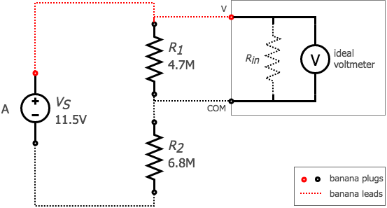
figure 15. Non-ideal Voltmeter Test Circuit
Turn the DC power supply back on and using the multimeter first measure the voltage across R1 and then move the multimeter to then measure the voltage across R2 and record both in the appropriate place on the results sheet.
Turn the DC power supply off and disconnect the circuit.
3.6 Clean-up
- Cleanup your station, everything should be returned to where you got it from. Verify your results with an instructor or TA to show that you have completed everything and once everything is completed and tidy get a signature on your Results page before you leave.
4 Post-Lab
The following is what you are expected to hand-in one week (by 4:00pm) after completion of the lab. You only have to hand-in one copy per group. There is an assignment box in the D-ICE pedway located just before the elevators marked ECE209 Lab. Please staple everything together in the following order:
Use the first page of your Result Sheet as your cover page. Make sure your names, student IDs, CCID’s and lab section are clearly writen in the table at the top of the page. Your results sheet should be signed twice by the laboratory instuctor or teaching assistant, once at the beginning of the lab to show that you have completed your prelab and once when you have completed the lab and finished cleaning up.
The remaining completed Results Sheets in order with all calculations, results and graphs as required.
The completed Post-lab Questions below on a separate piece of paper.
4.1 Calculations
Complete the tables on your Results sheet by completing the following calculations. Everything in light red on the results sheet is part of the postlab calculations.
Percent Error Calculation
\[\text{% Error} = \frac{\text{Measured}-\text{Actual}}{\text{Actual}}\]
For the RESISTORS A and B calculate the percent error of your resistor measurements.
For the Power Supply as a Voltage Source and Current Source calculate the difference error between your needle reading and your multimeter measurement.
For the Ohm’s Law and Power Dissipation calculate the resistance by using ohms law and the power by using the power equation.
For the Current Divider calculate the input power (PS), the power dissipated by each resistor (PR1 and PR2) and the total dissipated power (PR1 + PR2).
For the Voltage Divider calculate the input power (PS), the power dissipated by each resistor (PR1 and PR2) and the total dissipated power (PR1 + PR2).
For the Loading Effect calculate the percent error for your voltage measurements.
4.2 Graphs
Using the provided graphs in your results sheet make the following plots:
Resistor I-V Curves - Using the result from Ohms Law and Power create 3 separate plots showing each resistors (R1.8k, R4.7k and R20.0k) current vs. voltage.
Resistor P-V Curves - Using the result from Ohms Law and Power create 3 separate plots showing each resistors (R1.8k, R4.7k and R20.0k) power vs. voltage.
Current Divider - Current - Using the results from the Current Divider create 3 separate plots showing each branch current (IS, I1 and I2) vs. the resistance setting of R2.
Current Divider - Power - Using the results from the Current Divider create 3 separate plots showing each power (PR1+PR2, PR1 and PR2) vs. the resistance setting of R2.
Voltage Divider - Voltage - Using the results from the Voltage Divider create 3 separate plots showing each voltage (VS, V1 and V2) vs. the resistance setting of R2.
Voltage Divider - Power - Using the results from the Voltage Divider create 3 separate plots showing each power (PR1+PR2, PR1 and PR2) vs. the resistance setting of R2.
4.3 Questions
Answer the following questions on a separate piece of paper to hand in with your Results Sheet. Make sure to include an appropriate title, your first and last name, CCID, student ID and your lab section at the top of the page.
For the resistance measurements you took using your multimeter on both the 4-band and 5-band resistors do they fall within the tolerance boundries of the each Resistor? If not, explain.
Looking at the Resistor I-V Curves graph what does the slope of the each curve represent? Does each Resistor you plotted show a constant slope? If a Resistor doesn’t show a constant slope what does that mean? What does it mean if a resistor has a steep or a shallow slope? What does it mean if a resistor has a completely vertical or horizontal slope?
Looking at the Resistor P-V Curves graph the power is always positive. Explain in your own words what this means? What happens to the Power dissipated in the resistor when you double the voltage? Explain.
Using a 1/4 watt resistor across the terminals of channel A of the DC power supply what is the maximum resistance that can be used without exceeding its ratings and still be able to obtain the power supplies maximum current? Show your work.
Again using a 1/4 watt resistor across the terminals of channel A of the DC power supply what is the minimum resistance that can be used without exceeding its ratings and still be able to obtain the power supplies maximum voltage? Show your work.
What would the rating for power and resistance of a resistor placed across the terminals of channel A of the power supply be while you tried to draw maximum power? Show your work.
Looking at the results and graphs from the Current Divider do they support KCL (Kirchoffs Current Law)? Use your results to explain.
Looking at the results and graphs from the Voltage Divider do they support KVL (Kirchoffs Voltage Law)? Use your results to explain.
Using your measured results for VS, V1 and V2 from The Loading Effect calculate what the internal resistance of the non-ideal voltmeter is for both cases: the first is when you measured V1 and the second is when you measured V2. Show your work.