DC Power Supply
ECE209 - Fundamentals of Electrical Engineering
Electrical and Computer Engineering - University of Alberta
video 1. DC Power Supplies
1 DC Power Supply

Figure 1: Power Supply
The DC power supply used in our labs is the BK Precision 1651A Triple Output DC Power Supply. This page provides students with extra documentation for these power supplies, as well as an in-depth explanation of the features.
1.1 The Channels
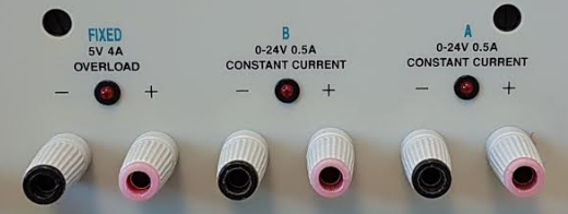
Figure 2: The Three Channels
DC power supplies will usually have multiple channels (voltage/current supplies that can work independently). In our labs the power supplies have three channels, these can be seen in the picture above with the three sets of black and red ports. You should notice that two of the channels are labelled “A” and “B”, while the third is labelled “FIXED”. This is because channels A and B are variable loads, they can produce an output that ranges anywhere from 0-24V (or from 0-0.5A), while the FIXED channel can only produce an output of 5V (up to 4A).
1.2 Voltage and Current Controls
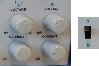
Figure 3: Voltage and Current Control Knobs/The A-B Switch
To change the voltage or current on channels A and B, you must use the voltage and current knobs located to the right of the channel ports. The knobs are labelled to correspond to either channel A or B, with the voltage control knob for each on top, and the current control knob below it. When setting the controls, ensure that neither the current nor the voltage are rotated completely to the left (there will be no output if voltage or current is zero).
To be able to see a change in the voltage or current of a channel, you must make sure that the A/B switch (located between the voltage and current meters) is set to the correct channel. This is very important and is often forgotten.
1.3 Tracking Modes
Figure 4: Tracking Mode Switch
The power supplies in this lab also have the ability to arrange the channels in series or parallel. By using the switch located above the control knobs, channels A and B can be put into different arrangements. The standard tracking mode is independent (switch pushed to the right); in this mode, both channels can operate independently from one another like we discussed above.
Moving the switch to the center position puts channels A and B in parallel with one another. This turns them into effectively one channel that can operate at 0-24V or 0-1A (double the normal current limit). In this mode, only the voltage and current controls for channel A will work. The voltage meter can be read as usual, but the reading from the current meter must be multiplied by 2. When using parallel tracking, the load being powered must be connected to the positive and negative terminals of channel A only.
Similarly, moving the switch to the left position puts channels A and B in series with one another. This allows them to supply from 0-48V (double the normal voltage limit) or 0-0.5A. Again only the channel A voltage and current control knobs work. The current meter can be read as usual in this mode, but the voltage reading must be doubled. To connect a load to this supply, you must connect the positive end to the positive terminal on channel A, and the negative end to the negative terminal on channel B.
1.4 Constant Voltage vs. Constant Current
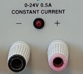
Figure 5: The Constant Current Indicator Light
Channels A and B can operate in two different modes: constant voltage mode and constant current mode. In constant voltage mode, the channel can be set to supply a certain voltage, and the current will change corresponding to the resistance of the load (think Ohm’s Law: \(V=IR\)). This is the mode that the supply is in by default.
If a threshold current is reached, the supply will switch over to constant current mode (where the current can be set to a specific value and the voltage will change depending on the load. The switch to constant current mode will be made clear by the red LED placed above the terminals for each channel.
To see what the threshold current is, short circuit the channel (connect a wire from the negative terminal to the positive terminal) and read from the current meter on the right. While the supply is short circuited, you can change the threshold current using the current control knob. This is useful when working with components that can only tolerate a certain amount of current, it can prevent you from accidentally burning them out.
1.5 The Ground
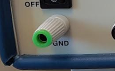
Figure 6: The Ground Terminal
The channels on this power supply are what is known as a “floating” power supply. This means that neither of the terminals are connected to the ground. Therefore, any voltage reading from these supplies is the potential difference between the positive and negative terminals, not the potential difference between the terminals and the ground.
The channels can be grounded by connecting the negative terminal to the ground terminal located on the bottom left of the power supply. A negative grounded supply could also be created by connecting the positive terminal to the ground terminal (the voltage at the negative terminal would then be negative with respect to the ground).