Lab 2: Circuit Theorems
ECE209 - Fundamentals of Electrical Engineering
Electrical and Computer Engineering - University of Alberta
1 Objectives
In this second lab session, you will continue to use the common electrical tools and components used for circuits in your Lab at Home kit and use them to experimentally test and confirm the validity of circuit theorems that are taught in the lectures. The objectives are as follows:
Introduce the following devices:
- 2nd DC Voltage Source - (WaveGen as DC Source)
Introduce the following concepts:
- Delta-Wye Transformations
- Superposition
- Thevenin’s Theorem
- Norton’s Theorem
- Thevenin-Norton Equivalency
- Maximum Power Transfer
1.1 Equipment Required
- The Lab 2 - Results sheet to record your measurements.
- A Computer with Waveforms installed
- Analog Discovery 2
- Breadboard Breakout for the Analog Discovery 2 with a Ribbon Cable
- A USB A to Micro-B cable
- Digital Multimeter
- MB102 breadboard
- DC Current Source
- Jumper Wires
- 1kΩ pot
- The following Resistors (1/4 watt, 1% or 5%)
- 24Ω
- 100Ω
- 220Ω
- two - 470Ω
- 680Ω
- 1kΩ
- 1.5kΩ
- 2.2kΩ
2 Procedures
2.1 Delta-Wye Transformations
Delta \(\rightarrow\) Wye transformation
Equations for transforming a Delta network into a Wye network,
\(\quad R1 = \dfrac{Rb\,Rc}{Ra + Rb + Rc}\)
\(\quad R2 = \dfrac{Ra\,Rc}{Ra + Rb + Rc}\)
\(\quad R3 = \dfrac{Ra\,Rb}{Ra + Rb + Rc}\)
Note: Transforming from Delta to Wye introduces one additional node.
Wye \(\rightarrow\) Delta transformation
Equations for transforming a Wye network into a Delta network,
\(\quad Ra = \dfrac{R1\,R2 + R2\,R3 + R3\,R1}{R1}\)
\(\quad Rb = \dfrac{R1\,R2 + R2\,R3 + R3\,R1}{R2}\)
\(\quad Rc = \dfrac{R1\,R2 + R2\,R3 + R3\,R1}{R3}\)
Note: Transforming from Wye to Delta removes one node.
Measure the resistance values of a wye connected resistor network shown below.

Circuit 1: Wye test circuit
Click here to compare wye and delta equivalent resistor networks.Connect the circuit above using the following:
Connect a 220Ω, 470Ω and the 1kΩ potentiometer as a wye on the breadboard.
Use the digital multimeter (DMM) to measure and record the resistance of R1, R2 and R3. When measuring R3 adjust the potentimeters knob until a resistance of ~321Ω is achieved between the center pin and the pin that connects to the other two resistors.
Use the DMM to now measure the resistance between the terminals labeled u-v, v-w and w-u and record your measurements on the results sheet.
Measure the resistance values of delta connected resistor network that is the approximate equivalent of the wye connected network from the previous step.

Circuit 2: Delta test circuit
Click here to compare wye and delta equivalent resistor networks.Before connecting the circuit above use the DMM as an ohmmeter to measure the resistors you are going to use for Ra, Rb and Rc and record those resistances on the results sheet.
Connect the resistors Ra, Rb and Rc that you measured above as a delta connected resistor network on the breadboard.
Use the DMM to now measure the resistance between the terminals labeled x-y, y-z and z-x and record your measurements on the results sheet.
2.2 The Test Circuit
Use the Test Circuit below as a starting point to accomplish 2 things: First to test if the Superposition Theorem is valid, then to see if Thevenin and Norton theorems are valid.

Figure 1: The test circuit

Circuit 3: The test circuit (shown with meter placement)
Click here to see a simulation demo of this circuit.Connect the circuit above using the following:
Use a 1.5kΩ resistor for R1, a 680Ω resistor for R2. For R_load start with a 100Ω resistor, you will switch out this resistor a few times for another value when required.
Use the positive DC voltage source from the Analog Discovery 2 as Va (V+ and Gnd). Set it to +5V but don’t enable it yet.
Use the ‘Wavegen’ channel 1 (W1) as a second positive DC voltage source from the Analog Discovery 2 for Vb (W1 and Gnd). Do not press Run yet but you can configure it with following parameters:
- Type = ‘DC’
- Offset = ‘3.3V’
Use Voltmeter channels 1 (1+ and 1-) and 2 (2+ and 2-) from the Analog Discovery to measure all the required voltages (Va, Vb, V_R1, V_R2 and V_load). You will have to move the opposite end of the 2 jumper wires that connect to the channel inputs (ie. 1+ and 1-) across the device you would like to measure one at a time.
Note: Voltage Polarity
As you will measure the voltage across the same location multiple times as the circuit changes slightly as you go through this laboratory exercise, you need to keep the measured polarities constant.
You can see in the circuit schematic above that each voltage that needs to be measured is represented as a voltmeter which also has a + and - near each terminal indicating which way you should make your measurement.
To be consistant always connect the voltmeter + input (ie. 1+ or 2+ on the Analog Discovery 2) to the side with the + symbol on the schematic. Do the same for the -.
Use the DMM as a milliammeter to measure all of the required currents (Ib, Ia and I_load). You will have to move the milliammeter to the appropriate place in the circuit to make the measurements one at a time.
Note: Moving the milliammeter
If you want to place the DMM into the circuit somewhere you need to break the existing circuit so you can insert the milliammeter.
If the DMM is a part of the circuit and you remove it you will create an open circuit where the milliammeter once was, you will need to replace the DMM with a shorting jumper wire to maintain the circuit.
Note: Current Polarity
As you will measure the current in the same location multiple times as the circuit changes slightly as you go through this laboratory exercise, you need to keep the measured polarities constant.
You can see in the circuit schematic above that each current that needs to be measured is represented by an ammeter with an arrow beside it. The arrow shows the polarity in which the measurement should be made.
To be consistant always connect the black lead of the DMM to the side with the arrow-head and the red lead to the opposite side. When connected this way the ammeter will give you a positive current when the current is traveling in the same direction of the arrow and a negative current when traveling in the direction opposite the arrow.
The circuit should look something like this when completed.
- Channel 1 is currently measuring V_R1
- Channel 2 is currently measuring V_R2
- The DMM is currently measuring Ib
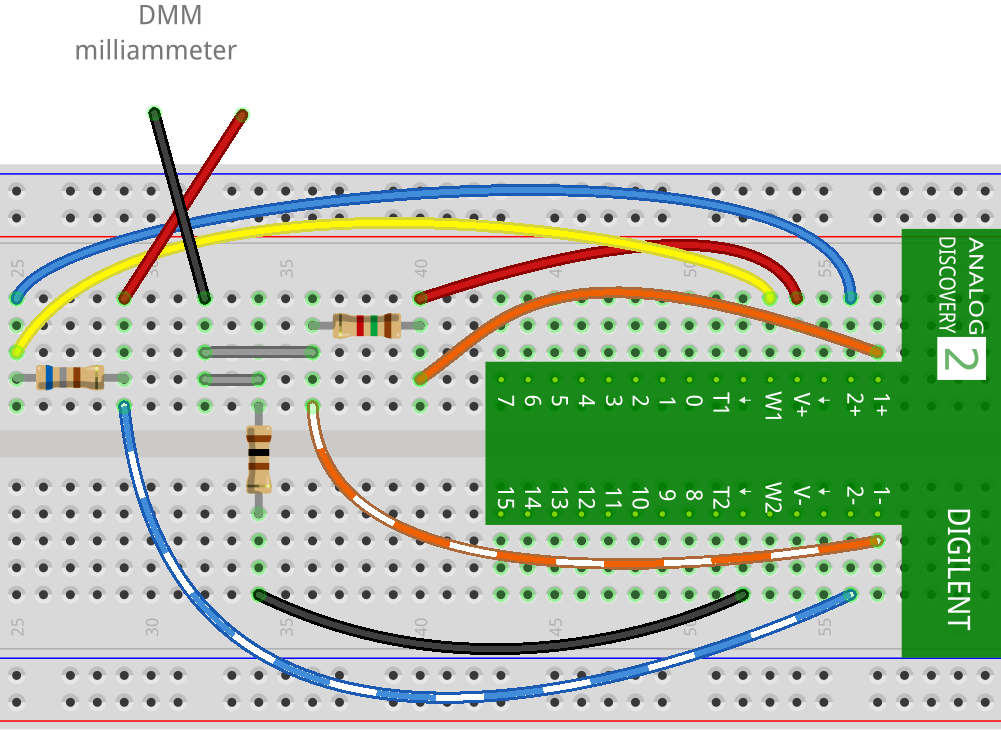
Figure 2: The test circuit shown on breadboard
- Activate both DC voltage sources in Waveforms by enabling the
required settings.
- On the ‘Supplies’ window select the appropriate enable buttons.
- On the ‘Wavegen’ window click on the run button, this should also check the checkbox automatically.
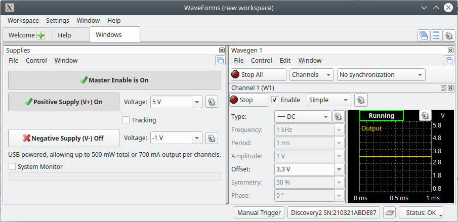
Figure 3: Using DC supplies on both the Supplies screen and Wavegen screen
Measure all voltages (Va, Vb, V_load, V_R1 and V_R2) and all of the currents (Ia, Ib and I_load) and record it on your results sheet for this value of R_load (100Ω).
Change the load resistor (R_load) to different values one at a time (220Ω, 470Ω, 1.0kΩ and 2.2kΩ) and make all of the same measurements again for each value making sure to record your measurement on your results sheet.
Note: Another way
Some people may find it easier/quicker to setup the voltmeters and ammeter to each measure a single measurement and then simply swap out the R-load resistor to get the measurements for the 5 different R_load values. Then move all of the meters to a new location and again get the measurements for different R_load values. Repeat until you have recorded all of the measurements required for The Test Circuit.
- After the completion of this section just turn off the voltage sources (Vb and Va) as you will continue to use this circuit in the Superposition section.
2.3 Superposition
Superposition Theorem
For a linear system the response (voltage or current) in any branch of a bilateral linear circuit having more than one independent source equals the algebraic sum of the responses caused by each independent source acting alone when all the other independent sources are replaced by their internal resistances.
2.3.1 Vb Acting Alone
To test superposition theorem you need to test the influence of each source on the circuit independently. Configure the Test Circuit from the previous step to see how the circuit responds when only supplied by Vb.

Figure 4: Vb acting alone circuit

Circuit 4: Vb acting alone circuit (showning meter placement)
Click here to see a simulation demo of this circuit.Make the following changes to the circuit from the previous step:
- Remove the Va voltage source from the circuit and replace it with a jumper wire to create a short circuit where the source once was. This is as easy as taking the one end of the red wire, from the test circuit breadboard diagram above, that is connected to V+ and moving it to Gnd.
Enable the Vb source and make all the same measurements as you did with the previous test circuit again with all of the different values of R_load. Make sure to record all your measurements on the results sheet.
After the completion of this section just turn off the Vb voltage source as you will continue to use this circuit in the next section.
2.3.2 Va Acting Alone
Now test for the second source in the circuit independantly; Configure the test circuit to see how the circuit responds when only supplied by Va.

Figure 5: Va cting alone circuit

Circuit 5: Va acting alone circuit (showing meter placement)
Click here to see a simulation demo of this circuit.Make the following changes to the circuit from the previous step:
Reconnect the Va voltage source to the circuit by reversing the connection you did in the previous step by moving the one end of the red wire back to the V+ input.
Remove the Vb voltage source from the circuit and replace it with a jumper wire to create a short circuit where the source once was. This is as easy as taking the one end of the yellow wire, from the test circuit breadboard diagram above, that is connected to W1 and moving it to Gnd.
Enable the Va source and make all the same measurements as you did with the previous test circuit again with all of the different values of R_load. Make sure to record all your measurements on the results sheet.
After the completion of this section just turn off the Vb voltage source as you will continue to use this circuit in the Equivalent Parameters section.
2.4 Thevenin/Norton
2.4.1 Equivalent Parameters
2.4.1.1 Voltage
The circuit below demonstates how to obtain the Thevenin Voltage for The Test Circuit as seen from R_load. To obtain the Thevenin Voltage the idea is to replace R-Load with an open circuit and then measure the voltage across that open circuit. The circuit below is identical to the circuits used in the previous sections with only a couple of differences: All of voltmeters and ammeters have been removed and the resistor R_load has been replaced by a voltmeter.

Circuit 6: Thevenin voltage circuit
Click here to see a simulation demo of this circuit.Make the following changes to the circuit from the previous step:
Reconnect the Vb voltage source to the circuit by reversing the connection you did in the previous step by moving the one end of the yellow wire back to the W1 input.
Remove all of the voltmeters and ammeters from the circuit.
Remove the resistor R_Load from the circuit and replace it with a DC voltmeter of your choosing (either the Analog Discovery 2 or the DMM). By placing the voltmeter where R_load would normally go creates an open circuit in that location as voltmeters typically have a very large input resistance.
Enable both voltage sources (Vb and Va) and the value measured on the voltmeter will be the Thevenin equivalent voltage. Record this measurement on your results sheet.
After you obtain your Thevenin Voltage just turn off both voltage sources (Vb and Va) as you will continue to use this circuit.
2.4.1.2 Current
The circuit below demonstates how to obtain the Norton Current for The Test Circuit as seen from R_load. To obtain the Norton Current the idea is to now replace R-Load with a short circuit and then measure the current going through that short circuit.

Circuit 7: Norton current circuit
Click here to see a simulation demo of this circuit.Make the following changes to the circuit from the previous step:
- Remove the voltmeter that you used to measure the Thevenin voltage and replace it with the DMM configured as a milliammeter. By placing the milliammeter where R_load would normally go creates a short circuit in that location as ammeters typically have a very small near 0Ω input resistance.
Enable both voltage sources (Vb and Va) and the value measured on the milliammeter will be the Norton equivalent current. Record this measurement on your results sheet.
After you obtain your Norton Current just turn off both voltage sources (Vb and Va) as you will continue to use this circuit.
2.4.1.3 Resistance
The circuit below demonstates how to obtain the Thevenin/Norton Resistance for The Test Circuit as seen from R_load using the 3rd method described below.
Note: Determining Thevenin/Norton Resistance
There are 3 common ways to determine this resistance:
By dividing the Thevenin-equivalent voltage by the Norton-equivalent current found in the previous steps. \[ R_{TH} = R_{NORTON} = \frac{V_{TH}}{I_{NORTON}}\]
By changing the resistance of R_load until the voltage across R_load is equal to half of the Thevenin-equivalent voltage. At this operating point the value of R_load is equivalent to RTH and RNORTON.
By replacing all of the sources with its internal resistance (ie. shorting all voltage sources and opening all current sources) and measuring the resistance at the terminals where R_load connects with R_load removed.

Circuit 8: Thevenin and norton resistance circuit
Click here to see a simulation demo of this circuit.Make the following changes to the circuit from the previous step:
Remove both the Vb and Va voltage sources from the circuit and replace them with a jumper wires to create a short circuit where the sources once were.
With the DMM still connected in the location of R_load rotate the DMM dial to the ohmmeter setting.
The value measured on the ohmmeter will be the Thevenin/Norton equivalent resistance. Record this measurement on your results sheet.
At this point double check your results to make sure you have everything required in the results sheet up to this point and that the measurements make sense to you. You can now disconnect this entire breadboard circuit as you will not need it anymore.
2.4.2 Thevenin Circuit
Thevenin’s Theorem
Thevenin’s Theorem states that any linear electrical network as seen from 2 nodes can be simplified to an equivalent circuit with just a single voltage source (VTH) in series with a resistance (RTH) and then connected to the load.
To demonstrate that the Thevenin equivalent circuit behaves the same as The Test Circuit as seen from R_load, connect the circuit below using the equivalent parameters you found in your tests from the previous section.

Circuit 9: Thevenin circuit
Click here to see a simulation demo of this circuit.Connect the circuit above using the following:
You can just use a single 470Ω as the thevenin resistor (R_th) as it should fall within the tolerance of the desired resistance. Before placing the resistor in the circuit measure it using the DMM as an ohmmeter and record the measurement on the results sheet.
Use the positive DC voltage source (V+ and Gnd) from the Analog Discovery 2 as V_th. Set it to Thevenin equivalent voltage determined in the previous section.
Measure the current (I_load) using the DMM as an milliammeter.
Measure the voltage (V_th) using channel 1 (1+ and 1-) of the ‘Voltmeter’ on the Analog Discovery 2.
Measure the voltage (V_load) using channel 2 (2+ and 2-) of the ‘Voltmeter’ on the Analog Discovery 2.
Start by using a 100Ω resistor for the value of R_load. You will switch out this load resistor a few times for another value when required.
Enable the appropriate DC voltage source in Waveforms and measure V_th, V_load and I_load and record it on the results sheet for this value of R_load = 100Ω.
Change the load resistor (R_load) the same way you did for The Test Circuit to different values one at a time (220Ω, 470Ω, 1.0kΩ and 2.2kΩ). Measure and record V_load and I_load on the results sheet for each load resistor.
After turning your voltage sources off and can now disconnect this entire breadboard circuit as you will not need it anymore.
2.4.3 Norton Circuit
Norton’s Theorem
Norton Theorem states that any linear electrical network as seen from 2 nodes can be simplified to an equivalent circuit with just a single current source (INORTON) and parallel resistance (RNORTON) connected to the load.
To demonstrate that the Norton equivalent circuit behaves the same as both the Thevenin Circuit and The Test Circuit as seen from R_load, connect the circuit below using the equivalent parameters you found in your tests from the previous section.

Circuit 10: Norton circuit
Click here to see a simulation demo of this circuit.First connect and test the current source by connecting the following:
- The LT3092 current source.

Figure 6: LT3092 shown on pcb
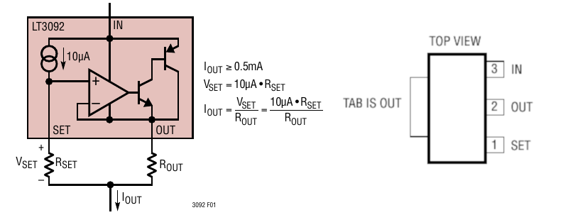
Figure 7: LT3092 (left = interal schematic, right = device pinout
A 20kΩ resistor as Rset at pin 1 (Set) of the device
A 24Ω resistor as Rout at pin 2 (Out) of the device, the other ends of both Rset and Rout need to get connected together.
Pin 3 (IN) of the device needs to get connected to the V+ of the Analog Discovery 2.
Connect the red probe of the DMM configured as a milliammeter to the Iout point in the diagram above. Connect the black probe to the V- pin of the Analog Discovery 2.
Your circuit should look something like this when completed.

Figure 8: Current source circuit shown on breadboard
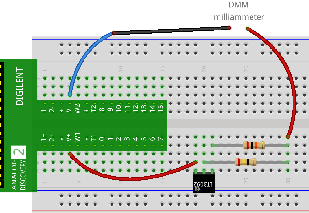
Figure 9: Current source circuit (same as breadboard
Test the current source by turning on both the positive and negative voltage supplies on the Analog Discovery 2 and you should get an approximate reading of 8.33mA on the DMM. Measure and record this value on your results sheet.
Now that your current source is setup and working continue by connecting the rest of the circuit:
You can use a single 470Ω as the norton resistor (R_norton) as it should fall within the tolerance of the desired resistance. Before placing the resistor in the circuit measure it using the DMM as an ohmmeter and record the measurement on the results sheet.
Measure the current (I_load) using the DMM as an milliammeter.
Measure the voltage (V_load) using channel 1 (1+ and 1-) of the ‘Voltmeter’ on the Analog Discovery 2.
Start by using a 100Ω resistor for the value of R_load. You will switch out this load resistor a few times for another value when required.
Enable the current source by enabling the positive and negative voltage sources in Waveforms (set to +5V and -5V) and measure V_load and I_load and record it on the results sheet for this value of R_load = 100Ω.
Change the load resistor (R_load) to different values (220Ω, 470Ω, 1.0kΩ and 2.2kΩ) one at a time the same way you did for the other tests. Measure and record V_load and I_load on the results sheet for each load resistor.
After turning your voltage sources off and can now disconnect this entire breadboard circuit as you will not need it anymore.
2.4.4 Thevenin-Norton Equivalency
Source Transformations
Performing a source transformation consists of using Ohm’s law to take an existing voltage source in series with a resistance, and replacing it with a current source in parallel with the same resistance, or vice versa. The transformed sources are considered identical and can be substituted for one another in a circuit.
Norton \(\rightarrow\) Thevenin conversion \[V_{th} = I_{norton} \times R_{norton}\] \[R_{th} = R_{norton}\]
Thevenin \(\rightarrow\) Norton conversion \[I_{norton} = \frac{V_{th}}{R_{th}}\] \[R_{norton} = R_{th}\]
2.5 Maximum Power Transfer
Maximum Power Transfer
The Maximum Power Transfer Theorem states that the maximum amount of power will be dissipated by a load resistance if it is equal to the Thevenin or Norton resistance of the network supplying power. The Maximum Power Transfer Theorem does not satisfy the goal of maximum efficiency.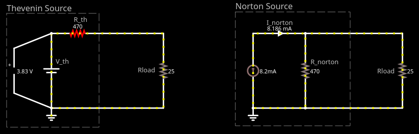
Circuit 11: Maximum Power Transfer Simulation
Click here to compare the maximum power transfer for equivalent thevenin and norton source circuits.
2.6 Cleanup
Congratulations, you have completed the experimental part of the laboratory. Before cleaning up, I’d suggest going through your results to check that you have completed everything and that your results make sense. If you find any issues, I’d suggest resolving or making a note of it now. If you are not continuing to work with the equipment please disconnect everything and put it away to prevent it from getting damaged.
3 Post Lab
The following is what you are expected to complete and submit for grading for Lab 2 before the deadline:
The completed Lab 2 - Results sheet template provided at the beginning of this lab manual under Equipment required. This sheet should include the following:
- Your name, student ID and CCID.
- All of the required measurements from the lab procedures.
- All of the required calculations as discussed below.
- The required plots as discussed below.
The Lab 2 - Results sheet needs to be submitted to the Submit (Lab 2 - Results) link on eClass as a pdf document .
Complete the online Quiz (Lab 2 - Post Lab) on eClass.
3.1 Calculations
For these calculation you only need to provide the answers in the space provided on your results sheet, you do not need to show your work.
For the Delta-Wye Transformations under Wye use the Delta-Wye transformation equations to calculate the equivalent Wye values for R1, R2 and R3 from the measured Delta resistance values Ra, Rb and Rc.
From your calculated values of R1, R2 and R3 from the previous step, calculate what the resistance between the terminals labelled u-v, v-w and w-u should be.
For the Delta-Wye Transformations under Delta use the Wye-Delta Transformation equations to calculate the equivalent Delta values for Ra, Rb and Rc from the measured Wye resistance values R1, R2 and R3.
From your calculated values of Ra, Rb and Rc from the previous step, calculate what the resistance between the terminals labelled x-y, y-z and z-x should be.
For Superposition complete the Superposition (Vb Acting Alone + Va Acting Alone) by summing the values of each cell in the Vb Acting Alone table with the corresponding cell in the Va Acting Alone table.
For the Thevenin Circuit calculate the power supplied by the voltage source (P_source) and the power dissipated by the load (P_load) for each value of R_load. Then calculate the overall efficiency of the circuit.
For the Norton Circuit calculate the power supplied by the current source (P_source) and the power dissipated by the load (P_load) for each value of R_load. Then calculate the overall efficiency of the circuit.
3.2 Plots
To create your plots you can use whichever software you would like (Excel, Matlab, etc), export your plot as an image and import it into your Lab 2 - Results sheet in the appropriate place.
Your plots should include:
- A Plot title
- Label your axes and show what unit of measure is used.
- Include a marking for your datapoints.
- Include a line between your datapoints in the same series.
- Include a legend.
- Make sure your scales are appropriate and visible.
Characteristic Plot: For each of these 3 circuits: The Test Circuit, Thevenin Circuit and Norton Circuit plot the load current vs. load voltage on the same plot.
Thevenin Circuit Plot: Plot the load power vs. load resistance as one series and the circuit efficiency vs. load resistance as a second series using a secondary y-axis scale.
Norton Circuit Plot: Plot the load power vs. load resistance as one series and the circuit efficiency vs. load resistance as a second series using a secondary y-axis scale.
3.3 Questions
Complete the online Quiz (Lab 2 - Post Lab) on eClass.