Lab 2 - Circuit Theorems
ECE202 - Electrical Circuits I
Electrical and Computer Engineering - University of Alberta
1 Objectives
The second lab session will have the students test and confirm the validity of concepts learned in the lectures. The objectives for this lab are therefore to:
Verify the Superpostion Theorem by making measurements on a circuit with two sources active. Then repeating the measurements twice, once with each source set to zero and demostrating that adding these measurements gives you a similar result as the initial measurements.
Verify Thevenin’s Theorem by comparing the results of the circuit used in the Superposition test and comparing it to a test completed with its Thevenin-equivalent.
Verify Thevenin’s and Norton’s Equivalency by measuring the results of two circuits that are said to be equivalent.
Demonstrate the Maximum Power Transfer Theorem and a circuits Efficiency by using a variable load resistor.
These objectives should be kept in mind as the students work through the lab procedure.
2 Pre-Lab
Before attending the lab, please complete the following:
Note:
Labs are typically completed in groups of two, so please try to pair up before coming to the lab. Each student needs to complete the pre-lab and hand it in at the start of their scheduled lab session. Only one lab report is required to be handed-in per group which is due one week after the schedule lab session. If you can’t find a partner we will either pair you up in the lab or you may also be permitted to work by yourself if there is an available station.
Completely read through the information discussed in the Background section below.
Familiarize yourself with the Equipment used in the first lab by going though the pages for each piece of equipment in the Equipment List.
Make sure you have either an electronic device with you where you can access this lab manual or print out the Lab 2 - Manual before coming to your lab section.
Make sure you print out a Lab 2 - Results Sheet to record all of your results. You only require one printout per group.
Complete these Pre-lab Questions on a seperate piece of paper to hand in at the beginning of your lab session. Make sure to include an appropriate title, your first and last name, CCID, student ID and your lab section at the top of the page. Everything in light green on the results sheet is what you should have filled in as well for your prelab.
For the Superposition Test Circuit in the lab procedures calculate the voltage across and the current through each one of the resistors using superposition when RLOAD equals 1000. Show all of your work and copy your final results into the appropriate place on the results sheet.
For the Superposition Test Circuit find equivalent VTH and INORTON as well as RTH/RNORTON. Show all of your work and copy your final results into the appropriate place on the results sheet.
What are the three different strategies describe in the lab procedures for measuring RTH/RNORTON.
2.1 Background
2.2 Equipment List
3 Procedure
3.1 Superposition
Superposition Theorem
For a linear system the response (voltage or current) in any branch of a bilateral linear circuit having more than one independent source equals the algebraic sum of the responses caused by each independent source acting alone when all the other independent sources are replaced by their internal resistances.
3.1.1 Superposition Test Circuit
Connect the superposition test circuit as an example circuit to obtain the initial measurements to verify the Superposition Theorem.
Use the appropriate resistors on the student printed circuit board for R1 and R2.
Use the DC power supply channels A and B for the DC sources VA and VB respectively. To set the voltages for each source use the multimeter as a DC voltmeter to assist in setting the corresponding values. Record your measurement values in the appropriate place in the results sheet. Make sure both of the current limits of the DC power supply are set to approximately 50% so they don’t interfere with the experiment. Make sure to not change these voltage setting during the experiment.
Use the decade box for RLOAD.
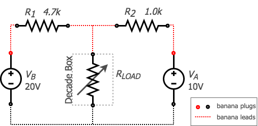
figure 1. superposition test circuit
Using the multimeter as a DC voltmeter measure the voltage across resistor R1 for the 5 different setting of RLOAD:
For RLOAD = Open - disconnect one of the banana leads from the Decade Box.
For RLOAD = 4000, 2000 and 1000 Ω - reconnect the banana leads to the Decade Box and apply the appropriate setting.
For RLOAD = Short - connect the two banana leads going to the Decade Box together.
Record your measurement of VR1 for each RLOAD setting in the appropriate place in the results sheet.
Note:
When taking measurements it is important to note the polarity or direction of both the voltage and current measurements. To do this you need to indicate/remember which lead of multimeter (red/black) connects to which end of the device you are measuring and also record the polarity (+/-) that the multimeter indicates. This should be done the same for all three superposition test circuits.- Continue in a similar fashion to measure the voltage across R2 and RLOAD as well as the current through R1, R2 and RLOAD for all 5 different settings of RLOAD.
3.1.2 Source VB Acting Alone
To verify the Superposition Theorem we will need to show how each individual source contributes to the circuit. First turning off voltage source VA to measure how source VB contributes to the circuit.
To “turn off” source VA it will need to be set to zero. The easiest way to do this is by removing the banana lead connected to the red ‘+’ on the DC power supplies channel A and plugging it in to the banana lead already connected to the black ‘-’ of the same channel which effectively shorts out the VA supply.
Below is the new test circuit with VB acting alone and VA set to zero.
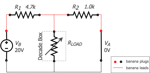
figure 2. VB acting alone
Measure VB to show it hasn’t changed since the last circuit and measure VA to show that it is now set to 0 volts. Record your measurements in the appropriate place on the results sheet.
Using the same procedure as the previous circuit measure the voltage across and the current through all of the resistors R1, R2 and RLOAD for all 5 different settings of RLOAD and record your measurements in the appropriate place on the results sheet.
Note:
Make sure that the measurements for this new circuit reflect the same polarity or direction as your measurements from the previous circuit.
3.1.3 Source VA Acting Alone
Now to show the contribution of VA to the circuit VB will need to be turned off.
Restore VA to the circuit by moving the appropriate banana lead from the black ‘-’ banana plug on channel A of the DC power supply to the red ‘+’ one.
Set VB to zero by moving the banana lead on the red ‘+’ banana plug on channel B of the DC power supply to the black ‘-’ one effectively shorting out this source.
Below is the new test circuit with VA acting alone and VB set to zero.
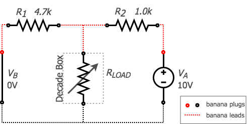
figure 3. VA acting alone
Measure VA to show it hasn’t changed since the fircuit circuit and measure VB to show that it is now set to 0 volts. Record your measurements in the appropriate place on the results sheet.
Using the same procedure as the previous two circuits measure the voltage across and the current through all of the resistors R1, R2 and RLOAD for all 5 different settings of RLOAD and record your measurements in the appropriate place on the results sheet.
Note:
Make sure that the measurements for this new circuit reflect the same polarity or direction as your measurements from the previous two circuits.
3.2 Thevenin and Norton Theorems
3.2.1 Finding Thevenin-Equivalent Voltage
Thevenin’s Theorem
Thevenin’s Theorem states that any linear electrical network as seen from 2 nodes can be simplified to an equivalent circuit with just a single voltage source (VTH) in series with a resistance (RTH) and then connected to the load.
Find the Thevenin-equivalent voltage for the superposition test circuit.
Restore VB to the circuit by moving the appropriate banana lead from the black
-banana plug on channel B of the DC power supply to the red+one.Replace RLOAD with the multimeter as a DC voltmeter.

figure 4. finding Thevenin-equivalent voltage
- The measured open circuit voltage is the Thevenin-equivalent voltage (VTH). Record this measurement in the appropriate place on the results sheet.
3.2.2 Finding Norton-Equivalent Current
Norton’s Theorem
Norton Theorem states that any linear electrical network as seen from 2 nodes can be simplified to an equivalent circuit with just a single current source (INORTON) and parallel resistance (RNORTON) connected to the load.
Find the Norton-equivalent current for the superposition test circuit.
- Replace the DC voltmeter with a DC ammeter.
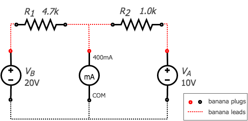
figure 5. finding Norton-equivalent current
- The measured short circuit current is the Norton-equivalent current (INORTON). Record this measurement in the appropriate place on the results sheet.
3.2.3 Finding Thevenin/Norton Equivalent Resistance
Thevenin/Norton Equivalent Resistance
Thevenin and Norton resistances are equal. Thevenin voltage is equal to Norton current times Norton resistance. Norton current is equal to Thevenin voltage divided by Thevenin resistance.
Find the Thevenin and Norton equivalent resistance for the superposition test.
There are 3 different ways to determine this resistance value:
By dividing the Thevenin-equivalent voltage by the Norton-equivalent current found in the previous steps. \[R_{TH} = R_{NORTON} = \frac{V_{TH}}{I_{NORTON}}\]
By changing the resistance of RLOAD until the voltage across RLOAD is equal to half of the Thevenin-equivalent voltage. At this operating point the value of RLOAD is equivalent to RTH and RNORTON.
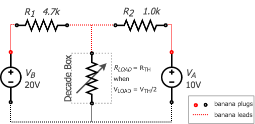
figure 6. finding Thevenin and Norton resistance #2
- By replacing all of the sources with its internal resistance (ie. shorting all voltage sources and opening all current sources) and measuring the resistance at the terminals.
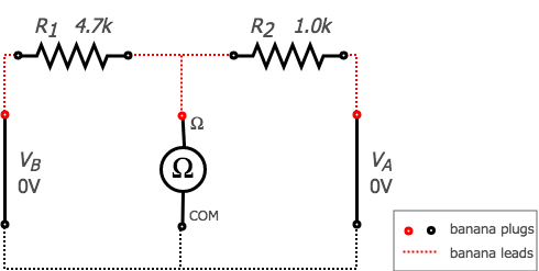
figure 7. finding Thevenin and Norton resistance #3
Complete the 3 methods above for determining the Thevenin and Norton equivalent resistance for the superposition test circuit and record your results in the appropriate place on the results sheet.
3.2.4 Testing Thevenin’s Theorem
Connect the new Thevenin test circuit to demonstrate that it behaves the same as the superpositon test circuit as seen by the Load.
Using one to the DC power supply channels as the source use the multimeter as a DC voltmeter to assist in setting the corresponding Thevenin-equivalent voltage (VTH). Make sure the current limit of the DC power supply are set to approximately 50% so they don’t interfere with the experiment. Make sure to not change the voltage setting during the experiment.
For Thevenin-equivalent resistor (RTH) use the same two resistors (R1 = 4.7k and R2 = 1.0k) in parallel.
Use the decade box as RLOAD.
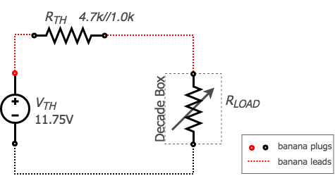
figure 8. testing Thevenin’s theorem test circuit
Using the multimeter as a DC voltmeter measure the voltage across resistor RLOAD for the 5 different setting of RLOAD:
For RLOAD = Open - disconnect one of the banana leads from the Decade Box.
For RLOAD = 4000, 2000 and 1000 Ω - reconnect the banana leads to the Decade Box and apply the appropriate setting.
For RLOAD = Short - connect the two banana leads going to the Decade Box together.
Record your measurement of VLOAD for each RLOAD setting in the appropriate place in the results sheet.
For the same 5 different setting of RLOAD measure the current through RLOAD using the multimeter as an milliammeter. Record your measurements of ILOAD for each RLOAD setting in the appropriate place in the results sheet.
3.3 Thevenin-Norton Equivalency and Maximum Power Transfer
Maximum Power Transfer Theorem
The Maximum Power Transfer Theorem states that the maximum amount of power will be dissipated by a load resistance if it is equal to the Thevenin or Norton resistance of the network supplying power. The Maximum Power Transfer Theorem does not satisfy the goal of maximum efficiency.
3.3.1 Thevenin’s Test Circuit
Thevenin-equivalent and Power Transfer Circuit
Using one to the DC power supply channels as the voltage source use the multimeter as a DC voltmeter to assist in setting the corresponding Thevenin source voltage to 5V. Record your measureed value in the appropriate place in the results sheet. Make sure the current limit of the DC power supply is set to approximately 50% so it doesn’t interfere with the experiment. Make sure to not change the voltage setting during the experiment.
Use one of the 100 resistors on the student printed circuit board for the Thevenin resistor (RTH).
Use the decade box as RLOAD.
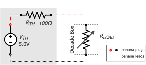
figure 9. Thevenin test circuit
Using the multimeter as a DC voltmeter measure the voltage across resistor RLOAD for the 9 different setting of RLOAD:
For RLOAD = Open - disconnect one of the banana leads from the Decade Box.
For RLOAD = 1600, 800, 400, 200, 100, 50, 25 Ω - reconnect the banana leads to the Decade Box and apply the appropriate setting.
For RLOAD = Short - connect the two banana leads going to the Decade Box together.
Record your measurement of VLOAD for each RLOAD setting in the appropriate place in the results sheet.
For the same 9 different setting of RLOAD measure the current through RLOAD using the multimeter as an milliammeter. Record your measurements of ILOAD for each RLOAD setting in the appropriate place in the results sheet.
3.3.2 Norton’s Test Circuit
Norton-equivalent and Power Transfer Circuit
Using one to the DC power supply channels as the current source use the multimeter as a DC milliammeter to assist in setting the corresponding Norton Current source value to 50mA. Record your measured value in the appropriate place in the results sheet. Make sure the voltage limit of the DC power supply is set to approximately 50% so it doesn’t interfere with the experiment. Make sure to not change the current setting during the experiment.
Use one of the 100 resistors on the student printed circuit board for the Norton resistor (RNORTON).
Use the decade box as RLOAD.
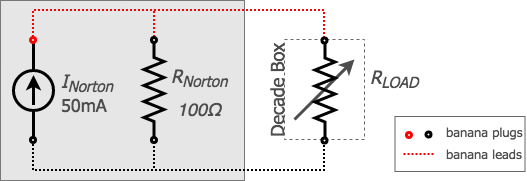
figure 10. Norton test circuit
Using the multimeter as a DC voltmeter measure the voltage across resistor RLOAD for the 9 different setting of RLOAD:
For RLOAD = Open - disconnect one of the banana leads from the Decade Box.
For RLOAD = 1600, 800, 400, 200, 100, 50, 25 Ω - reconnect the banana leads to the Decade Box and apply the appropriate setting.
For RLOAD = Short - connect the two banana leads going to the Decade Box together.
Record your measurement of VLOAD for each RLOAD setting in the appropriate place in the results sheet.
For the same 9 different setting of RLOAD measure the current through RLOAD using the multimeter as an milliammeter. Record your measurements of ILOAD for each RLOAD setting in the appropriate place in the results sheet.
3.4 Clean-up
- Cleanup your station, everything should be returned to where you got it from. Verify your results with an instructor or TA to show that you have completed everything and once everything is completed and tidy get a signature on your results page before you leave.
4 Post-Lab
The following is what you are expected to hand-in one week (by 4:00pm) after completion of the lab. You only have to hand-in one copy per group. There is an assignment box in the D-ICE pedway located just before the elevators marked ECE202 Lab. Please staple everything together in the following order:
Use the first page of your Result Sheet as your cover page. Make sure your names, student IDs, CCID’s and lab section are clearly writen in the table at the top of the page. Your results sheet should be signed twice by the laboratory instuctor or teaching assistant, once at the beginning of the lab to show that you have completed your prelab and once when you have completed the lab and finished cleaning up.
The remaining completed Results Sheets in order with all calculations, results and graphs as required.
The completed Post-lab Questions below on a separate piece of paper.
4.1 Calculations
Complete the tables on your results sheet by completing the following calculations. Everything in light red on the results sheet is part of the postlab calculations.
Sum the measurements from Superposition Test Circuit: (VB acting alone) to the the corresponding measurements from Superposition Test Circuit: (VA acting alone) and place the results in the appropriate table (VB acting alone + VA acting alone) on the results sheet.
Calculate the percent difference between the two results from the Superposition Test Circuit and place the results in the appropriate table on the results sheet.
\[\text{% difference} = \frac{(V_A\text{ acting alone}+V_B\text{ acting alone})-\text{measured}}{\text{measured}}\]
Calculate the percent difference between the measured VLOAD for the Superposition Test circuit and the Testing Thevenin’s Theorem for each of the different RLOAD settings. Do the same for ILOAD. Record your results in the appropriate place on the results sheet.
Calculate PS, PLOAD and Efficiency for the Testing Thevenins Theorem circuit for each of the different RLOAD settings and place the results in the appropriate place on the results sheet.
\[P_S = V_{IN}\times{I_{IN}} = V_{TH} \times I_{LOAD} = P_{IN}\] \[P_{LOAD} = V_{LOAD} \times I_{LOAD} = P_{OUT}\] \[\text{efficiency} = \frac{P_{OUT}}{P_{IN}}= \frac{P_{LOAD}}{P_S}\]
Calculate PS, PLOAD and Efficiency for the Thevenin’s Test Circuit for each of the different RLOAD settings and place the results in the appropriate place on the results sheet.
Calculate PS, PLOAD and Efficiency for the Norton’s Test Circuit for each of the different RLOAD settings and place the results in the appropriate place on the results sheet.
4.2 Graphs
Using the provided graphs in your results sheet make the following plots:
Thevenin I-V Characteristic Curve - Using the measurements from the Thevenin’s Test Circuit, plot ILOAD vs. VLOAD on the provided graph on your results sheet.
Thevenin Load Curve and Efficiency - Using your calculations from the Thevenin’s Test Circuit, make two plots on the provided graph on your results sheet: First, plot POUT vs. RLOAD. Second, plot Efficiency vs. RLOAD.
Norton I-V Characteristic Curve - Using the measurements from the Norton’s Test Circuit, plot ILOAD vs. VLOAD on the provided graph on your results sheet.
Norton Load Curve and Efficiency - Using your calculations from the Norton’s Test Circuit, make two plots on the provided graph on your results sheet: First, plot POUT vs. RLOAD. Second, plot Efficiency vs. RLOAD.
4.3 Questions
Answer the following questions on a separate piece of paper to hand in with your Results Sheet. Make sure to include an appropriate title, your first and last name, CCID, student ID and your lab section at the top of the page.
How does the Superposition Test Circuit measurments compare with the sum of your measured VA acting alone and VB acting alone? Explain any discrepancies in your results.
How do your results of Testing Thevenin’s Theorem Circuit compare to the Superposition Test Circuit? Does the Thevenin Circuit seem to look perform the same as seen by RLOAD?
On the Thevenin and Norton I-V Characteristic Curves there are diagonal load lines drawn on the plots. Explain in your own words what these lines represent and how do they interact with your results.
Comparing the Thevenin I-V Characteristic Curve to the Norton Characteristic curve? Would you say that these circuits perform equivalently? Explain.
Looking at both the Thevenin and Norton Load Curves what is the value of RLOAD which gives the maximum power to RLOAD? What is the efficiency at this operating point? How does this value of RLOAD compare with the values of RTH and RNORTON?
Looking at the efficiency plots for both Thevenin and Norton explain in your own words what the difference is and how this comes about?