Digital Multimeter
ECE202 - Electrical Circuits I
Electrical and Computer Engineering - University of Alberta
video 1. Digital Multimeters
Fluke 175 Digital Multimeter

Figure 1: Fluke 175 True RMS Multimeter
Basic Features
Digital multimeters are used to perform a large variety of measurements including voltage, current, resistance and more.
The DMMs used in our labs have four terminals with which connections can be made, a rotary dial for selecting the type of measurement, as well as a few buttons to access different measurement modes.
The terminal in the bottom right corner of the DMM is the common terminal (COM for short). This will be used in all measurements. The red VΩ terminal above it is used for all measurements except for current, and the two red terminals on the left are used for AC and DC current measurements.
The COM terminal and the VΩ terminal are connected with a very large resistance between them, this simulates an open circuit and allows the DMM to work similarly to an ideal voltmeter.
The COM terminal and the 400mA/10A terminals are connected with a very small resistance between them, this simulates a short circuit and allows the DMM to act similarly to an ideal ammeter. As you can see on the lines drawn between them, there are internal fuses between these terminals and the COM terminal. This prevents the DMM from being damaged if too high of a current is measured.
Resistance Measurements
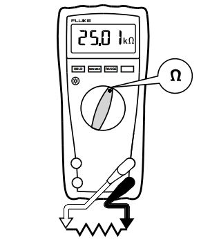
Figure 2: Measuring Resistance with a DMM
To measure a resistance, follow these steps:
Turn off the power supply to your circuit (if there is one)
Set the rotary dial to Ω.
Using wires in the VΩ and COM terminals, connect the meter to both ends of the resistance. Direction is not important, resistance is an absolute value.
Read the value from the screen.
Important: You must not have any power supplied to your load while you are measuring its resistance. The meter measures resistance by outputting a set voltage to the load, and then measuring the current that responds.
Voltage Measurements
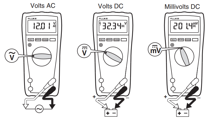
Figure 3: Measuring Voltages with a DMM
To measure a voltage across a load, follow these steps:
Turn off the power supply to your circuit.
Set the rotary dial to correct type of voltage. For DC voltage select the V (mV for small voltages) with a straight line above it. For AC voltages select the V with a wavy line above it.
Plug wires into the black COM terminal and the red VΩ terminal.
Use those wires to place your meter in parallel with the voltage you are trying to measure.
Turn the power supply back on.
Read the value from the screen.
Important: For positive voltage readings, the voltage should be higher at the red VΩ terminal than the black COM terminal.
Current Measurements
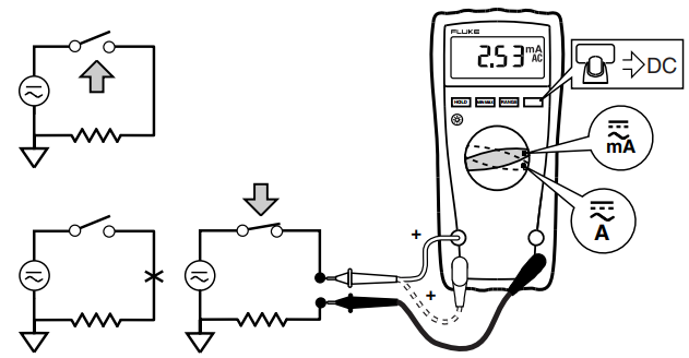
Figure 4: Measuring Current with a DMM
To measure the current through a load, follow these steps:
Turn off the power supply to your circuit.
Set the rotary dial to mA if you are measuring small currents, and A if you are measuring large currents (we will use mA in this lab)
If you are measuring DC current, press the yellow button below the screen (this is indicated by the yellow symbols above the mA and A).
Disconnect the circuit at the point you are measuring.
Insert the wire from the circuit into the black COM terminal.
For currents less than 400mA, plug a wire into the 400mA terminal. For currents greater than 400mA and less than 10A, plug a wire into the 10A terminal. (in this lab, the 400mA terminal is best).
Use that wire to reconnect the circuit. This places the meter in series with your circuit.
Turn the power supply back on.
Read the value from the screen.
Important: For positive current readings, the current should flow from the red 400mA (or 10A) terminal to the black COM terminal.