EE 552
2-D Room Mapper
Project Final Report
Shaun Luong
Clifton Yeung
Jon Paul Kansky
Patrick Asiedu-Ampem
Abstract
For our EE 552 project, we successfully
designed, built, implemented and tested a 2-Dimensional Room Mapper. The
majority of the system was implemented using an Altera UP1 Educational
board featuring the Altera FLEX EPF10K20RC240-4 FPGA. The 2-D Room Mapper,
using ultrasonic sound waves, has the capability of finding the distance
between itself and any sound-reflecting object, such as a point on a wall.
It is also able to reposition its transmitter and receiver to take readings
of other points along the walls of a room. These readings are displayed
on a VGA monitor for the operator to record. From the data collected, the
layout of a room can be acquired.
In designing the system, we developed several smaller individual
components to do portions of the overall desired functionality of the 2-D
Room Mapper. We then instantiated all these smaller components to build
the 2-D Room Mapper. The components that we developed and implemented using
the FPGA includes the controller, clock dividers, a stepper motor controller,
a transmitter pulse generator, a distance finder, a timer, a position counter
with a BCD converter, and a video display driver. Components of the system
that are external to the FPGA include the ultrasonic transmitter and the
ultrasonic receiver circuits, the stepper motor and driver circuit, the
on-board 7-segment LED displays, and the on-board input push buttons and
switches. The essential component of both transmitter and receiver circuits
is a pair of ultrasonic transducers. All of these smaller parts of our
design are brought together to build a 2-D Room Mapper.
Description
Overview
The 2-D Room Mapper was designed to calculate the distance between
itself and a point on the wall. In order to do this, the 2-D Room Mapper
utilizes a set of ultrasonic tranducers to send and detect ultrasonic waves.
We based our project on the basic principle that sound waves can be bounced
(reflected) off walls. By measuring the times between sending an ultrasonic
wave and the detection of the its reflection, the distance can be easily
calculated. In theory, by rotating the transducers (ultrasonic transmitter/receiver)
by 10° in between readings, the Mapper can collect 36 points of data,
allowing the general layout of a room to be known. The 2-D Room Mapper's
range finding capabilities is limited to approximately 3 meters. This limitation
is due to several factors, some of which include the type of ultrasonic
transducers used and the ability for the receiver circuit to amplify a
signal.
The implementation of the entire system is essentially done by the
FPGA. The FPGA houses the system controller, clock dividers, stepper motor
controllers, transmitter pulse generator, timer, distance finder, position
counter, LED display driver, and video display driver. External circuitry
such as switches, push buttons, and the transmitter/receiver circuits are
interfaced to the FPGA to complete our design.
Clock Divider
The clock divider was necessary to slow down the original clock on
board the Altera UP1 Educational Board. The original speed of the clock
is 25.175 MHz. This was faster than some of our components could run, so
we devised a way to slow the clock down. The system itself has a clock
speed of 12.5 MHz. The FPGA was also used to trigger the ultrasonic transmitter
at 40 kHz. The stepper motor uses a frequency of 5 Hz. The frequency required
had to be divisible by a factor of 2. The clock divider esstenially is
a pulse counter. It could be set to count N number of pulses before sending
one pulse out. This N is changed in the VHDL code for the different required
clock speeds:
|
Module
|
Desired
Frequency
|
Desired
Period
|
N
|
Actual
Frequency
|
Actual
Period
|
|
UP1 Board
|
25 MHz
|
40 ns
|
n/a
|
25.175 MHz
|
40 ns
|
|
FPGA
(System Clock)
|
12.5 MHz
|
80 ns
|
1
|
12.5875 MHz
|
80 ns
|
|
Transmitter
|
40 kHz
|
25 us
|
313
|
40.22 kHz
|
24.87 us
|
|
Stepper Motor
|
5 Hz
|
200 ms
|
2,500,000
|
5.04 Hz
|
198.6 ms
|
N ³ UP1 Board Frequency N integer
2*(Desired Module Frequency)
Transmitter Pulse Generator
The transmitter pulse generator essentially turns a transistor on and
off at a rate of 40KHz. This transistor in turns triggers the ultrasonic
transducers at 40KHz, which transmits that signal. The main building block
for this component is the clock divider previously discussed. We added
an enable to the pulse generator's clock divider to control its output.
Using the enable, the controller can control when the transducer sends
an ultrasonic wave. The transistor is triggered from the FPGA to saturate
the transistor, therefore shorting the voltage across the transducer, turning
it off. Below is the circuit that the pulse generator signal is sent to.

Receiver Circuit
The receiver circuit's main job is to amplify the signal received
by the ultrasonic transducer. The signal must be amplified to at least
the FPGA's threshold voltage in order to be detected. The circuit utilizes
two 741 OP-AMPs to obtain its gain. The amplification portion of this circuit
has a gain of a little over 400. A clipping circuit was also used at the
output of the amplification circuit to protect the FPGA from extreme inputs
such as voltage swings. The transducer in the receiver circuit is tuned
to receive only sound waves of 40KHz and has a bandwidth of 5KHz. The receiver
circuit is shown below.

Timer
The timer module counts the number of clock pulses between transmission
and reception of the ultrasonic pulse. A frequency of 12.5 MHz is used.
With the given frequency, a theoretical accuracy of 27.44um is possible.
The first problem with this measurement is the output from the op-amplifier.
The input into the FPGA is a sinusoidal wave, irrelevant of the transmitted
pulse. To trigger a logic level of '1' to the FPGA, a minimum value of
3.0 Volts is required. Assuming the pulse has a period of 0.025ms and a
maximum amplitude of 5 Volts, a rise time of 6.25us is determined. Given
that the speed of sound is 343 m/s, the maximum accuracy possible is about
2mm. A conservative estimate, given the quality of our components and delay
times, is an accuracy of 1cm.
Distance Finder
This arithmetic module calculates the distance from the Room
Mapper to an object in the ultrasonic transmitter's path. Knowing that
sound travels at 343 m/s and the clock frequency is 12.5MHz, the distance
can be calculated. The period of the clock is 80ns. By knowing these parameters
and using the system clock to track the time it takes between the transmission
and reception of the ultrasonic pulses, the distance to the wall and back
can be calculated. This distance is then divided by 2 to obtain the desired
information (transmission distance, not transmission and reception distance).
To avoid the costly division algorithm, we decided to count every second
clock pulse, thus essentially doing the division. The number of pulses
is obtained from the timer.
Sample Calculation
Distance = (Speed of Sound) x (clock period) x (number of clock pulses)
x (mm to m conversion)
= 343m/s x 80ns x (# of pulses) x 1000
Position Counter
The job of the position counter is to count the number of measurements
taken. It keeps track of the number of measurements taken and stops the
system after 36 readings. Each reading is approximately 10 degrees apart,
corresponding to 10 steps of the stepper motor used. It increments by 1
after each rotation.
LED Display Driver
The LED Display Driver is basically a BCD decoder which takes the number
from the position counter and displays it in decimal form on the 7-segment
displays attached on the Altera UP1 Educational Board. This portion is
a simple conversion found in several previous examples.
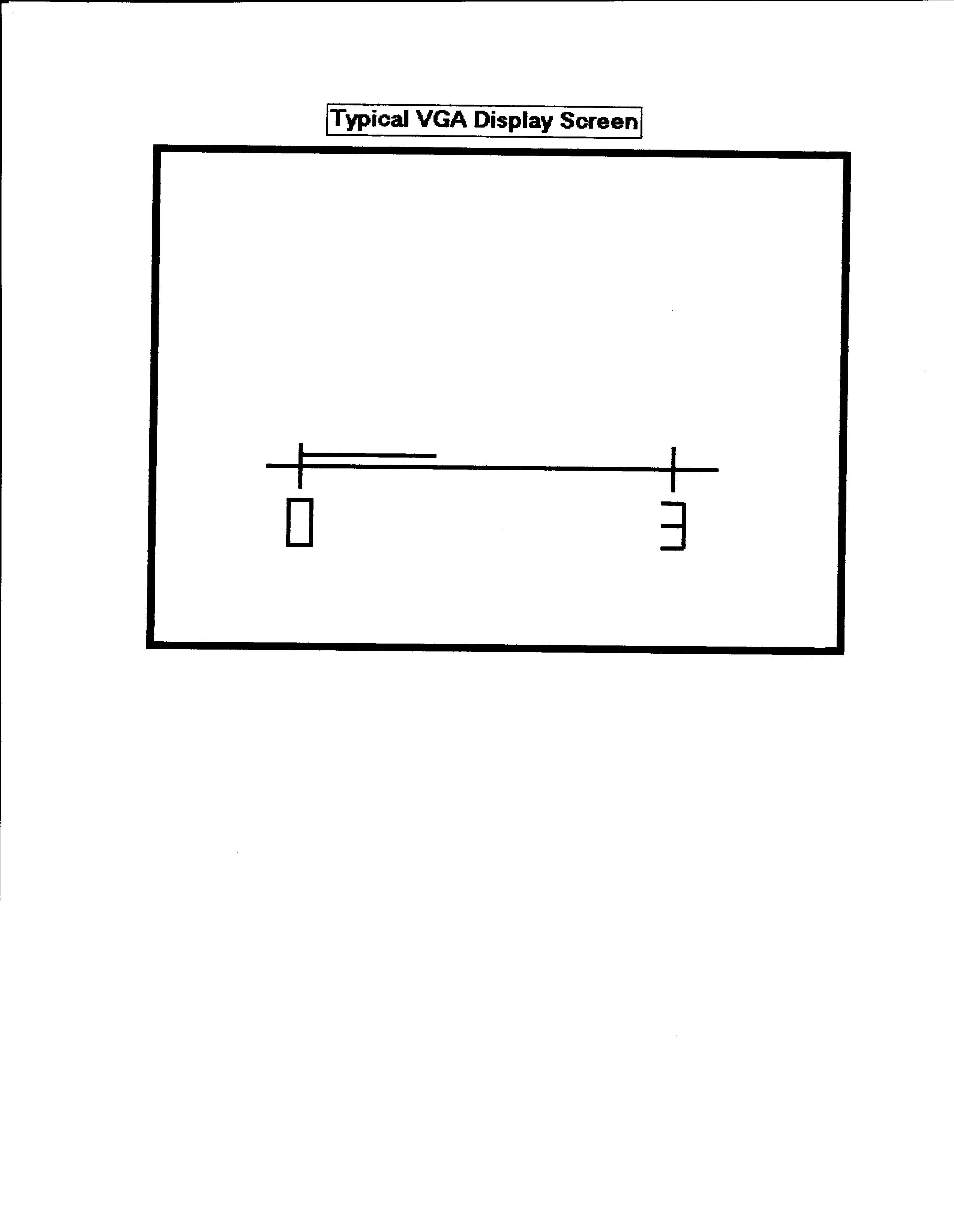
Video Display Driver
The video display driver takes the distance that was calculated by
the distance calculation module and displays it to a 640 x 480 VGA monitor.
The display driver displays a line proportional to the distance calculated.
It also displays a reference line to which can be compared to the calculated
line. The typical monitor display is as follows:
Stepper Motor Controller
The stepper motor requires its winding to be energized in a particular
sequence, dependent on its number of phases, in order for it to rotate.
The order in which the windings are energized also determines the direction
of rotation. The motor we used was a two-phase motor. In order for the
motor to rotate properly, we had to energize its windings in this particular
sequence:
|
PHASE 1
|
PHASE 2
|
Step 1
|
|
|
Step 2
|
***
|
|
Step 3
|
***
|
***
|
Step 4
|
|
***
|
We used the FPGA to trigger a set of transistors, which in turn
triggered relays to energize the coils. The circuit diagram below depicts
the circuit used to control the stepper motor.

Control System
The system controller is the brain of the entire system. It determines
what the 2-D Room Mapper will do when certain inputs are given. Inputs
into the system come from switches, push buttons, and the ultrasonic receiver
circuit. After being reset into the first state "startup", it
initializes all appropriate signals. It waits for a signal from the receiver
indicating that an ultrasonic pulse was received. At this point, it stops
the timer and disables the transmitter. When confirmation is received from
the distance finder that the multiplication has finished, it then sends
the value directly to the video display. The next step is to reset the
timer and rotate the motor 10 degrees. A counter is used to measure 36
points, corresponding to 360 degrees, after which the reset must be pressed.
The implementation of the system controller is in the form of a Moore Finite
State Machine (See Appendix A2). The FSM consists of 5 states, in which
certain components are to perform their specific tasks. The system controller
is implemented in such a way as to ensure proper data propagation by evaluating
handshaking signals from the different components.
Design Problems and Work-Arounds
Software
One problem we encountered was the need for different clock speeds.
Several components of our system needed different clock speeds. The transmitter
needed 40 kHz to transmit, the stepper motor was clocked at 5 Hz, the monitor
uses 25 MHz, and the controller uses 12.5 MHz. By designing a generic,
and very simple clock divider, several clock frequencies were outputted
using few logic cells. The only restrictionon the clock dividers is that
they had to be even factors of 25 MHz (i.e. 12.5 MHz, 6.25 MHz, etc.).
The original video display was to output numeric values on the screen.
Due to the lack of logic cells onthe Altera board, a simpler representation
of the distance was opted for. A line with values 0 and is echoed to the
screen, with a movable line that is displayed somewhere in between, corresponding
to the proper value.
The system controller, implemented as a Moore FSM, had to be revised
several times. Originally, we had planned on a "dance" state
after our system had finished measuring all 36 points, wherein the stepper
motor controller would enable the mapper to rotate wildly until the user
resets it. Due to time constraints, available wires, and the fact that
this state was not necessary, the "dance" state was eliminated
from the controller. However, another state did have to be added to allow
the user to record each distance measurement. Since our mapper did not
have any memory, only the current measurement would be displayed. At first,
the mapper was going to measure all 36 points without any user input in
between measurements. A "pause" state was added to allow the
user to record the current reading and prompt the mapper to go to the next
point. Implementing the controller as a FSM in Altera MaxPlus 2 using the
same style of coding as was used in Mentor Graphics did not work. The signals
would not properly hold their values in between states, and as an initial
work-around, these signal assignments were repeated for all the states.
A better work-around was achieved by taking the signal assignment statements
outside of the case structure (the way to implement a FSM in Mentor Graphics)
and putting them inside separate WITH/SELECT structures. This allowed MaxPlus
2 to properly interpret the controller as a FSM, and the signals were properly
held in between states.
Hardware
There were several problems we encountered while testing our
design. One was supplying enough current to both the stepper motor and
physical relays. The received signal also needed to be amplified to trigger
the FPGA.
To trigger the stepper motor, two signals representing the phases are
sent from the FPGA to the control circuitry of the stepper motor. The stepper
motor requires that the coils in the motor be energized in a certain order
and using a certain voltage. Two different power supplies had to be used
to supply the required voltage of +6 and -6 Volts. Two relays were connected
to another power supply of 10 Volts to the collector of the transistor.
The FPGA output signals trigger the base of transistor to turn the relays
on and off, therefore switching the motor coils to +6 and -6 Volts. This
circuit is excellent for isolating the FPGA from the high currents used
for the relay and motor. The transistor used for switching had to be rated
for a higher current due to the current used to energize the relay.
The transmitter circuit also used a transistor to switch the
transducer on and off. The transducer needs a voltage of 10 Volts to send
a pulse. The FPGA sends a 40 kHz pulse to the base of the transistor, causing
the current through the transistor to turn on and off. The transistor shorts
out the current to the transmitter, causing no voltage drop across the
transducer. This transistor is also great for isolating the FPGA from the
high current of the transmitter.
The receiver circuit is a little more complex than the transmitter
circuit. The output from the second op-amp is sufficient to drive the FPGA
from a max distance of 3 m. The difficulty in this design is that the voltage
is proportional to the distance the ultrasonic wave has to travel. At small
distances, the voltage can reach as high as 16 Volts peak to peak. This
output would fry the FPGA. A limiting circuit had to be designed to limit
the voltage into the FPGA between 0V and 5V. A diode was connected from
the output to ground to limit the low voltage to -0.7 Volts, within specifications
of the FPGA. The signal is not allowed to go higher than 5 Volts, therefore
a voltage divider is used to set a point at approximately 4 Volts. A diode
is then inserted from the output to that point to provide a high-end voltage
of 4.7 Volts.
Appendix
Bibliography
McComb, Gordan. Robot Builder's Bonanza: 99 Inexpensive Robotics
Projects. New York: TAB BOOKS, 1987.
A1
VHDL CODE
fpga.vhd
bcd.vhd
bi_count.vhd
clk_div.vhd
distance.vhd
monitor.vhd
motor2.vhd
rotater.vhd
timer.vhd
transmit.vhd