Lab 2 - Three Phase Diode Rectifiers
ECE401: Power Electronics
Electrical and Computer Engineering, University of Alberta

Figure 1. Typical laboratory setup for the three-phase diode rectifiers lab.
1 Introduction
The 3-Phase Diode rectifier is a widely used input stage for many high power applications requiring a high power DC supply. This laboratory obtains the performance and operating waveforms of the 3-phase diode rectifier using two different configurations: one uses an ac-supply reactor, dc-link output filter capacitor and a resistive load and the other replacing the ac-supply reactor with a dc-link inductor. You will obtain an appreciation of the rectifier input waveforms and the relationship between the input and output rms, ac and dc components of the current. These performances are monitored as a function of the rectifier input current over a range of load levels. During this lab you will also gain a respect for the per-unit system of specifying parameters relatively to the power rating of the device.
Below is a summary of what you will be working on during this laboratory.
- Fluke 43B setup.
- 3 Phase Supply Box.
- Two-wattmeter Method.
- Load Box Setup.
- Current limiting resistor.
Circuit 1: Reactor Inductance Test
Figure out the inductance of each phase of the 3 phase reactor while it is operating under typical conditions.
Circuit 2: with AC-Supply Reactor
Determine the performance of a 3-phase bridge diode-Rectifier with both a ac-supply reactor and a DC-link capacitor filter by loading it with a resistor load bank.
Circuit 3: With Inductor in DC-link
Compare the performance of the previous circuit to the same 3-phase bridge diode-Rectifier but with an inductance connected in the dc-link as opposed to the supply side.
1.1 Equipment
- Assorted Shielded Banana Test Leads
- Fluke 43B Power Quality Analyzer
- Fluke 80i-110s Current Probe
- Fluke 4mm Voltage Leads
- 3 Phase Supply Box
- 3-Phase Diode-Bridge Rectifier Box
- 3 Phase Resistor Load Box
1.2 Safety
Please watch the Safety Video before attending your lab session.
Remember the voltages (300VDC and 208VAC) that you are working with can cause serious harm to you if not respected. Please be careful with your hands and fingers around the circuits to avoid electrocution. If you run into any problems during your experiment disconnect power immediately.
Do not leave banana leads connected at only one end of the circuit with the other end floating around. This free end of the cable can potentially have voltage on it and create a dangerous hazard.
While working with these voltages that can possibly be exposed it is a good idea to remove any metal watches, rings, bracelets etc…
Understand the ratings and limitations of the equipment you are operating. Monitor your circuits closely and try to operate the equipment within specifications at all times.
The capacitor in the Diode Rectifier Box has a resistor in series with it. The resistors purpose is to limit the destructive inrush current that is associated with the charging of a capacitor. Therefore the switch must be in an open state to allow the current to be limited by the resistor at start-up. After the capacitor is charged the resistor must be shorted via the switch because the resistor is unable to handle the continuous power flow. Leaving the resistor in will cause errors in your results because you’re limiting the current available to the capacitor. Failure to do either step will damage the equipment!!!
Do not make changes to the circuit while power is applied. This doesn’t include changing load switches or moving your voltage/current probes around to make different measurements.
Make sure that all large capacitors are discharged before making changes to your circuit. Mainly this is the DC-Link Capacitor that needs to have a significant load on it to make sure it discharges in a reasonable amount of time.
Please keep your work area tidy while working on experiments.
Always have an Instructor or TA check your circuit changes before you apply power.
2 Pre-lab
Each student must complete a pre-lab to hand in at the beginning of your laboratory section. You must have completed all actions of the prelab before being allowed to participate in the Lab. The laboratory is usually completed in pairs, so please try and find a partner in the same lab section as you. See the Laboratory Schedule to make sure you show up to the correct time and place.
2.1 Pre-lab Reading
Familiarize yourself with the lab equipment, procedures, documents and results sheet.
Look at equipment pages to familiarize yourself with the equipment listed below that is used in Lab 2. Note that there are links to the lab equipment pages available.
Read over the entire lab manual so you understand what you will be undertaking during the lab.
Look at the provided ECE401 - Lab 2 - Results sheet to see what you will be recording as results during the laboratory.
Print off a ECE401 - Lab 2 - Sign-off sheet . You only need one per group.
2.2 Pre-lab Questions

Figure 2. (Pre-lab circuit) 3 Phase diode-bridge rectifier with capacitor filter and input reactor.
For the circuit above that is experimented on during this laboratory uses the approximate operating conditions below.
The 3ph supply voltage is 208VLL at 60Hz.
The resistive load is 60Ω
The input reactor is 5mH, and the filter capacitor is 1mF.
Ignore the forward voltage of the diode.
Assume a constant input power of 1240 W
Calculate or use the performance curves to obtain the following parameters (showing all of your work) to hand in at the beginning of the lab session. Copy your results to the appropriate column in the ECE401 - Lab 2 - Results sheet .
fO, VO,DC, ILOAD,DC
PLOAD – Assume an efficiency of 100%
μ (commutation overlap)
DPF, PF, CDF
PIN, SIN, THDF, IS, I1
2.2.0.1 Performance Curves
Note
The performance curves of the rectifier assume a constant input power where we can say PPU = 1.0.
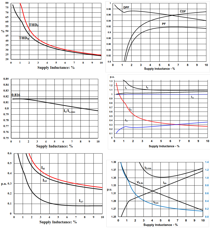
Figure 3. Performance curves for a 3-phase
diode-bridge rectifier with an ac supply reactor and a dc filter
capacitor.
Taken from Section 4 of the ECE 401 notes.
3 Experimental Procedure
Danger!
The power used in this lab can cause severe electrocution that can lead to serious injury or even death. So please follow instruction carefully and be cautious with your experiments.
Have an Instructor or TA verify your circuit connections before you apply power!!!
3.1 Equipment Familiarization
It is good practice when working with equipment that has a danger associated with it that you familiarize yourself with the use, function and safety precautions necessary to operate the equipment in a manner which will keep the equipment in good working order and the user safe.
3.1.1 Fluke 43B and Current Probe
Setup the Fluke 43B and the current probe in the same manner that was done in lab 1.

Figure 4. Current Probe, Fluke 43B Power Quality Analyser, Test Leads and the Power Adaptor for the Fluke 43B.
Take the Fluke 43B out of the case and connect the following:
The power supply to the device and an electrical outlet.
The test leads with the 4mm probe tips to channel 1.
The current probe to channel 2 using the supplied BNC adaptor.
Turn on the Fluke 43B and configure the current probe by:
Turn on the current probe to 10mV/A and make sure the Fluke 43B is setup to use the same by going to ‘Instrument Setup/Probes’ in the ‘Main Menu’.
Zero the current probe using the dial on the current probe and also note the arrow on the current probe to specify the currents polarity.
Set the function preferences as follows:
Harmonics (%f) (DC .. 21).
Power (Full).
3.1.2 3 Phase Supply Box
A fused 15A 208VLL three-phase supply is available from the red, black and blue shielded banana jacks. The output voltage can be turned on/off by the buttons marked start and stop. Notice the red light indicating when the power is on. A earth ground connection is also included on the box with a green shielded banana jack, which is used to ground the chassis/enclosure of any high-powered equipment.

Figure 5. 3ph Supply Box.
- Use the Fluke 43B to measure the output voltage (208VLL) for all 3 phases, and the operation of the on/off switch. Is the supply working properly? – If not notify a lab instructor or TA.
3.1.3 Two-Wattmeter method
The two-wattmeter method is used to accurately measure power in 3-phase 3-wire circuits. To measure the total input power into the diode rectifier you will be using this technique. Normally this technique uses 2 wattmeter’s to make these measurements at the same time. Due to the availability of only one wattmeter we will need to make one power measurement and then move both the voltage and current probes carefully to make the other power measurement. To do this first connect the Fluke 43B probes to measure IA and VAB and get the 1-ph power measurement from the Fluke 43B, then move the probes to measure IC and VCB and get the corresponding. The total input power is simply the sum of the two. The polarity of both the voltage and current probes need to be correct in order for the two measurements to add correctly.

Figure 6. Method for using 2 single phase wattmeter measurements to measure the 3 phase power.
Note
Due to the circuit parameters constantly changing due to circuit temperature fluctuations, it is good practice to take these two measurements fairly quickly one after another.
3.1.4 Load Box Setup
For a 3 phase diode rectifier connected to a supply voltage of 208 VLL the approximate output voltage (~ 294 VDC) can easily exceed the maximum rated voltage of one of the load boxes banks (~ 183 VRMS). Therefore, it is required that 2 of the banks get connected in series, as shown below, so the load on withstand the voltage delieverd to it by the rectifier.
- Calculate the new maximum voltage capability of this load box configuration.

Figure 7. Two resistor banks in series to increase the voltage capability of the load.
- With the load box connected as shown above measure the resistance at the terminals connected to the DC-Link for each load step using the Fluke 43B. Note which steps correspond with the required steps in the Results Table.
Note
It is good practice to begin experiments under no-load or a light load power (small currents using a large load resistance). This means having no or one load switch on initially and as you further load your circuit (higher power by switching in more load resistors in parallel in the load box) you should carefully watch your currents and voltages to make sure none of the circuit ratings are exceeded during your experiment.
3.1.5 Current Limiting Resistor
This is a reminder to use the inrush current limiting limiting resistor the same way you did in lab 1. Here it is even more important as the DC-link voltage is much higher than in lab 1.
Warning
The capacitor in the Diode Rectifier Box has a resistor in series with it. Its purpose is to limit the potentially large destructive inrush current that occurs when initially charging a large capacitor at start-up. Therefore the switch must be in an open state (down position) at start-up to allow the current to be limited by the charging resistor. After the capacitor is charged, the resistor must be shorted with the switch (up position). Note that if the resistor is left un-shorted during the experiment, it will overheat and possibly fail as it is unable to handle the power losses during continuous operation. Lastly, if you leave the resistor un-shorted you will be changing the operation of the rectifier and your results will be incorrect!

Figure 8. The inrush current limiting resistor and its bypass switch.
3.2 Reactor Inductance Test
Connect the circuit as shown in Circuit 1. Make sure the power is off.
Use the appropriate colored shielded banana leads to connect 3ph supply to the 3ph reactor in the 3-Phase Diode-Bridge Rectifier Box.
Connect the other end of the 3ph reactor also using the appropriate colored shielded banana leads to the 3ph resistor load box which is connected in a wye configuration.
Make sure to connect the gound chassis terminals of the rectifier box and load box to the earth ground connection on the 3ph supply box.
Start with all of the load box switches in the off position.
Warning
Get a lab instructor or TA to check your circuit before you energize.

Circuit 1. Reactor inductance test circuit.
Click here
to see a simulation demo of this
circuit.
Turn on the power supply and using the switches on the load box increase the supply current until you get approximately 4 ARMS going through each limb of the reactor. Use the Fluke 43B to measure the fundamental voltage across, the fundamental current through and phase angle between the two for each limb of the reactor and record your measurements in the appropriate table on the results sheet.
Once all the required measurements are obtained and checked and can turn off the 3ph power supply.
3.3 with AC Supply Reactor
Connect the circuit as shown in Circuit 2. Make sure the power is off.
- Using the 3ph Supply Box, the 3-Phase Diode-Bridge Rectifier Box and the 3 Phase Resistor Load Box configured as shown below. Connect the circuit shown in Circuit 2 below using the appropriate colored shield banana leads.

figure 9. Connect two load banks in series to increase the loads voltage capability.
Make sure to connect the ground chassis terminals of the rectifier box and load box to the earth ground connection on the supply box.
Start with all of the load box switches in the off position.
Note
Double check that your current probe zeroed, it is important to check that the current probe is zeroed every once and awhile during your experiments, especially before you attempt measurements with any DC current component in them.
Warning
Get a lab instructor or TA to check your circuit before you energize.

Circuit 2. 3-phase Diode Rectifier with AC-Supply
Reactor
Click here
to see a simulation demo of this
circuit.
Danger!
Do not make changes to the circuit while power is applied.
You can move the Fluke 43B probes and change the load box setting while power is applied but please be careful.
Warning
If you turn off the power for any reason during your experiment make sure to use the inrush current limit resistor switch as required.
If your circuit is correct and you have verified that the inrush current limit resistor switch is in the proper position for start-up. Apply power and wait approximately 2 seconds for the capacitor to fully charge and then use the switch to short out the current limiting resistor. The 3 phase bridge rectifier should now be operational.
Complete the AC Supply Reactor portion of the table on the results sheet. Make sure to complete an entire column for one load setting before moving on to the next one. During the measurements you will need to move both the voltage probes and current probe around to obtain the desired measurement. You will also need to change the screens and settings on the fluke 43B so the desired measurement can be obtained.
Capacitor current
Note that you can measure the capacitor current by using the current probe around 2 wires at the same time as shown in the picture below.

Figure 10. Using the current probe to measure the capacitor current.
When you finish all of the measurements required for this section, turn off the supply, then reset the capacitor current limit switch and turn off all of the load box switches. Leave your circuit connected as you will be modifying it in the next section.
Before you move on to the next section verify your results with an Instructor or TA and get them to sign your results sheet.
3.4 with Inductor in DC-Link
Reconfigure your previous circuit to construct Circuit 3. Make sure the power is off.
Remove the 3-phase reactor from the input of the diode rectifier and use it as a dc-link inductor as shown in Circuit 3. Only use the outer limbs of the reactor in your circuit while leaving the middle limb unconnected. Make sure to reconnect the 3ph supply box to the inputs of the 3 phase bridge diode rectifier.
Start with all of the load box switches in the off position.
Note
Double check that your current probe zeroed, it is important to check that the current probe is zeroed every once and awhile during your experiments, especially before you attempt measurements with any DC current component in them.
Warning
Get a lab instructor or TA to check your circuit before you energize.

Circuit 3. 3-Phase Diode Rectifier with a DC-Link
Inductor
Click here
to see a simulation demo of this
circuit.
If your circuit is correct and you have verified that the inrush current limit resistor switch is in the proper position for start-up. Apply power and wait approximately 2 seconds for the capacitor to fully charge and then use the switch to short out the current limiting resistor. The 3 phase bridge rectifier should now be operational.
Complete the DC Inductor portion of the table on the results sheet. Make sure to complete an entire column for one load setting before moving on to the next one. During the measurements you will need to move both the voltage probes and current probe around to obtain the desired measurement. You will also need to change the screens and settings on the fluke 43B so the desired measurement can be obtained.
When you finish all of the measurements required for this section, turn off the supply, then reset the capacitor current limit switch and turn off all of the load box switches.
Before you move on to the next section verify your results with an Instructor or TA and get them to sign your results sheet.
3.5 Clean-Up

Figure 11. Return safety banana lead and the test leads to the wall, place the Fluke 43B back in the case as shown and return the 4mm test probes to the box.

Figure 12. Leave the remaining equipment tidy on the workbench.
If you are finished make sure you put everything back to where you got it before you leave. Please make sure that the current probe is turned off.
Remember to log-off or shutdown the computer.
Have a lab instructor or TA sign your results sheet to ensure that you have cleaned everything up properly before you leave.
4 Post-lab
The following is what you are expected to hand-in approximately one week after completion of the lab, check eClass for the exact time and date. All reports need to be submitted to the appropriate link on eClass. You only have to hand-in one copy per group. Please have your pages in a single pdf file in the following order:
Use a scanned/picture of your ECE401 - Lab 2 - Sign-off sheet as your cover sheet. Make sure that you have obtained the required lab sign-off signatures at the bottom of the page. Also make sure that all of your group members names, CCID’s and lab section are visible in the table at the top of the page.
The completed ECE401 - Lab 2 - Results sheet .
The answers to the post-lab questions.
4.1 Questions
Explain in your own words, how changing the rectifier input power changes the value of the supply inductance in per-unit? Note that a high input power is associated with a low value of the load resistance, and a low input power is associated with a high value for the load resistance. (5 marks)
Explain how increasing the per-unit supply inductance will affect the following circuit parameters (assume a constant input power), explain your answers: (10 marks)
- Total harmonic distortion of the current (THDF)
- DPF, CDF and PF
- IS,pu, IS1,pu, IS5,pu and IS7,pu
- Rectifier output voltage, Vo,dc
What range of per-unit supply inductance is suitable for a 3-phase rectifier? Explain why your answer is desirable. (5 marks)
The maximum power factor you can get for large values of per unit inductance using a dc-link inductor is 0.955 and for an ac-supply reactor the maximum is 0.920. Using the curves for total harmonic distortion and power factor explain in your own words why in the lab you observe that the power factor decreases when power decreases. (5 marks)
Comparing the dc output voltages for both the ac-supply reactor and dc-link inductor cases. Explain in your own words why in the ac-supply reactor circuit the output voltage falls with increasing power while in the dc-link inductor circuit the output voltage stays relatively flat. (5 marks)