Lab 2: Circuit Theorems
ECE202 - Electrical Circuits I
Electrical and Computer Engineering - University of Alberta
1 Objectives
In this second lab session, you will continue to use the common electrical tools and components used for circuits in your Lab at Home kit and use them to experimentally test and confirm the validity of circuit theorems that are taught in the lectures. The objectives are as follows:
Introduce the following concepts:
- Delta-Wye Transformations
- Superposition
- Thevenin’s Theorem
- Norton’s Theorem
- Thevenin-Norton Equivalency
- Maximum Power Transfer
1.1 Equipment Required
- The Lab 2 - Results sheet to record your measurements.
- USB Power Supply
- A USB A to Micro-B cable
- Micro USB Breakout Board
- Digital Multimeter (User Manual )
- MB102 breadboard
- DC Current Source (User Manual )
- Jumper Wires
- 1kΩ pot
- The following Resistors (1/4 watt, 1% or 5%)
- 10Ω
- 100Ω
- 220Ω
- 470Ω (two)
- 680Ω
- 1.0kΩ (two)
- 1.5kΩ
- 2.2kΩ
- 10kΩ
2 Procedures
2.1 Delta-Wye Transformations
Delta \(\rightarrow\) Wye transformation
Equations for transforming a Delta network into a Wye network,
\(\quad R1 = \dfrac{Rb\,Rc}{Ra + Rb + Rc}\)
\(\quad R2 = \dfrac{Ra\,Rc}{Ra + Rb + Rc}\)
\(\quad R3 = \dfrac{Ra\,Rb}{Ra + Rb + Rc}\)
Note: Transforming from Delta to Wye introduces one additional node.
Wye \(\rightarrow\) Delta transformation
Equations for transforming a Wye network into a Delta network,
\(\quad Ra = \dfrac{R1\,R2 + R2\,R3 + R3\,R1}{R1}\)
\(\quad Rb = \dfrac{R1\,R2 + R2\,R3 + R3\,R1}{R2}\)
\(\quad Rc = \dfrac{R1\,R2 + R2\,R3 + R3\,R1}{R3}\)
Note: Transforming from Wye to Delta removes one node.
Measure the resistance values of a wye connected resistor network shown below.

wye test circuit
Connect the circuit above using the following:
Connect a 220Ω, 470Ω and the 1kΩ potentiometer as a wye on the breadboard.
Use the digital multimeter (DMM) to measure and record the resistance of R1, R2 and R3. When measuring R3 adjust the potentiometers knob until a resistance of ~321Ω is achieved between the center pin and the pin that connects to the other two resistors.
Use the DMM to now measure the resistance between the terminals labeled u-v, v-w and w-u and record your measurements on the results sheet.
Measure the resistance values for the delta connected resistor network that is the approximate equivalent of the wye connected network from the previous step.

delta test circuit
Before connecting the circuit above use the DMM as an ohmmeter to measure the resistors you are going to use for Ra, Rb and Rc and record those resistances on the results sheet.
Connect the resistors Ra, Rb and Rc that you measured above as a delta connected resistor network on the breadboard.
Use the DMM to measure the resistance between the terminals labeled x-y, y-z and z-x and record your measurements on the results sheet.
2.2 The Test Circuit
Use the Test Circuit below as a starting point to accomplish 2 things: First to test if the Superposition Theorem is valid, then to see if Thevenin and Norton theorems are valid.
Click here to see a simulation demo of this circuit.

the test circuit
Connect and test the voltage and current source on the breadboard:
Use the USB breakout board and Power supply for the 5V DC voltage source labeled V1.
Use the DMM as a DC voltmeter to measure the output voltage of the USB power supply and record the result in the appropriate spot on the results sheet.
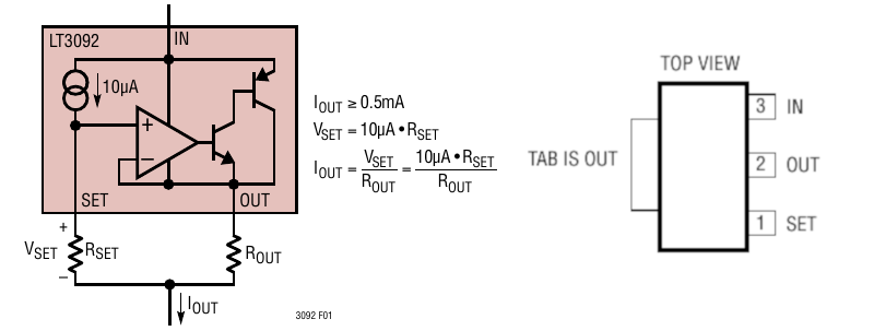
Use the LT3092 current source with a 10Ω resistor for Rout and a 2.2kΩ in series with a 1.0kΩ for Rset. Power the current source from the USB power supply by connecting the 5V to IN. Using these resistors to set the current source the resultant current should be approximately 3.3mA.

Use the DMM as a DC milliammeter to measure the actual current of the current source and record the result in the appropriate spot on the results sheet.
At this point your circuit should look something like the following:

setup voltage and current source
Connect the rest of the circuit:
Remove the DC milliammeter.
Use a 680Ω resistor for R_a and a 1.5kΩ resistor for R_b. For R_load start with a 100Ω resistor, you will switch out this resistor a few times for another value when required. Use jumper wires to connect the resistors together so the jumper wires can easily be replaced with an ammeter when required to measure the currents I_a, I_b and I_load.
Your circuit should now look something like this:

the test circuit (initial position)
Note: Making Measurements
For most of the circuits in the lab we need to make multiple measurements, both currents and voltages, and then repeat those same measurements again with different resistance values for R_load. To do this it is easier/quicker to setup the circuit to make a certain measurement (e.g. I_a) and then swap out the R_load resistor to make that measurement multiple times for different load resistors. The alternative is to move the meter around multiple times for each load resistor, but to move an ammeter around and to change it back and forth between a voltmeter and ammeter takes more time and is more prone to mistakes.
Setup the DMM as a DC voltmeter and measure the voltage across the resistor R_a and record that voltage in the appropriate place in the results sheet. See the note below about voltage and current polarities to make sure you record the correct sign.
Note: Voltage and Current Polarities
As you will measure the voltage across and current through the same location multiple times as the circuit changes slightly as you go through this laboratory exercise, you need to keep the measured polarities constant. In all of circuit schematic’s the polarity for the measurements you need make are identified.
For the voltage it is identified as a + and - next to each terminal of the resistor. To be consistant use the red DMM input to connect to the plus and the black DMM input to the minus everytime you make a voltage measurement.
For the current it is identified with an arrow. When making a current measurement connect the black DMM input on the node in which the arrow points and connect the red DMM input on the opposite node.
While still measuring the voltage across R_a replace the R_load resistor, first with a 220Ω, then a 470Ω, and finally with a 1.0kΩ. Recording your DC voltage measurement for each load resistor value (R_load = 100Ω, 220Ω, 470Ω and 1.0kΩ) in the appropriate place on the results sheet.
Move the DMM to measure the DC voltage across the R_b resistor, which is also the voltage across the R_load resistor and current source as they are all in parallel. Measure and record the voltage across resistor R_b on your results sheet for the same 4 values (R_load = 100Ω, 220Ω, 470Ω and 1.0kΩ) as you did in the previous step.
To measure the current I_a we will need to open the yellow jumper wire and replace it with the DMM configured as a DC milliammeter. To do this, disconnect only the one end of the yellow jumper wire connected to the resistor R_a and insert the DMM in the broken path with the black DMM input connected to the yellow jumper wire and the red DMM input connected to the resistor R_a. Making sure the DMM is configured as a DC milliammeter, measure and record the current through resistor R_a on your results sheet for the same 4 values (100Ω, 220Ω, 470Ω and 1.0kΩ) of R_load as you did in the previous step.
- Your circuit should now look something like this:

measure current I_a
Note: Moving the milliammeter
If you want to place the DMM into the circuit to measure current somewhere you need to break the existing circuit so you can insert the milliammeter.
Restore the circuit by removing the DMM and replacing the yellow jumper wire. Insert the DMM in the circuit to measure the current I_b by disconnecting the blue jumper wire and inserting the DMM in the polarity indicated on the schematic. Measure and record the current through resistor R_b on your results sheet for the same 4 values (R_load = 100Ω, 220Ω, 470Ω and 1.0kΩ) as you did in the previous step.
Restore the circuit again. Insert the DMM in the circuit to measure the current I_load using a similar procedure in the previous steps this time using the green jumper wire. Measure and record the current through resistor R_load on your results sheet for the same 4 values (R_load = 100Ω, 220Ω, 470Ω and 1.0kΩ) as you did in the previous steps.
Remove the DMM and restore the test circuit so all of the jumper wires are in there initial position.
You will continue to use a modified version of this circuit in the Superposition section. If you would like to turn off the power to your circuit simply unplug the USB cable from the power supply.
2.3 Superposition
Superposition Theorem
For a linear system the response (voltage or current) in any branch of a bilateral linear circuit having more than one independent source equals the algebraic sum of the responses caused by each independent source acting alone when all the other independent sources are replaced by their internal resistances.
2.3.1 V1 Acting Alone
To test superposition theorem you need to test the influence of each source on the circuit independently. Configure the test circuit from the previous step to see how the circuit responds when only supplied by V1.
Click here to see a simulation demo of this circuit.

V1 acting alone circuit
To test what influence the V1 voltage source has on the circuit we need to remove all other sources. Superposition states that all other voltage sources should be replaced with short circuits and all other current sources should be replaced with open circuits. To do this, we will need to remove the current source from the previous circuit and replace it with an open circuit. This can simply be done by removing the orange jumper wire from the test circuit.
- Your circuit should now look something like this:

breadboard V1 acting alone circuit
Make sure that the USB power is supplied and follow a similar procedure as the previous section to make all the same measurements (V1, VR_a, VR_b, I_a, I_b, I_load) for all of the same resistors loads (R_load = 100Ω, 220Ω, 470Ω and 1.0kΩ). Make sure to record all of your measurements in the appropriate place on the results sheet.
Remove the DMM and restore the test circuit so all of the jumper wires are in there initial position.
You will continue to use a modified version of this circuit in the I2 Acting Alone section. If you would like to turn off the power to your circuit simply unplug the USB cable from the power supply.
2.3.2 I2 Acting Alone
Now test what influence the I2 current source has on the circuit independently; Configure the test circuit from the previous steps to see how the circuit responds when only supplied by I2.
Click here to see a simulation demo of this circuit.

I2 acting alone circuit
To test what influence the I2 current source has on the circuit we need to remove all other sources. To do this, we will need to remove the voltage source from the test circuit and replace it with a short circuit. To do this we can not simply disable or short the 5V voltage source as it is used to power the current source, so we need to remove it from the circuit entirely. To do this we are simply going to move the R_a resistor so the end that was connected to the 5V of V1 will now connect directly to Gnd.
- Your circuit should now look something like this:

breadboard I2 acting alone circuit
Make sure that the USB power is supplied and follow a similar procedure as the previous sections to make all the same measurements (I2, VR_a, VR_b, I_a, I_b, I_load) for all of the same resistors loads (R_load = 100Ω, 220Ω, 470Ω and 1.0kΩ). Make sure to record all of your measurements in the appropriate place on the results sheet.
Remove the DMM and restore the test circuit so all of the jumper wires are in there initial position.
You will continue to use a modified version of this circuit in the Equivalent Parameters section. If you would like to turn off the power to your circuit simply unplug the USB cable from the power supply.
2.4 Thevenin/Norton
2.4.1 Equivalent Parameters
2.4.1.1 Voltage
The circuit below demonstrates how to obtain the Thevenin Voltage for The Test Circuit as seen from R_load. To obtain the Thevenin Voltage the idea is to replace R-Load with an open circuit and then measure the voltage across that open circuit. The circuit below is identical to the circuits used in the previous sections except that the resistor R_load has been replaced by a voltmeter.
Click here to see a simulation demo of this circuit.

thevenin voltage circuit
You can try and make this measurement if you like but you will obtain an incorrect value. This is due to the current source needing more voltage than the 5V source can supply to maintain the 3.3mA current source. The actual current from the current source will be something smaller with no R_load resistor present.
To get the value you need for this section obtain the Thevenin Voltage (V_th) using the simulation demo above. Record the V_th equivalent parameter in the appropriate place on the results sheet.
2.4.1.2 Current
The circuit below demonstrates how to obtain the Norton Current for The Test Circuit as seen from R_load. To obtain the Norton Current the idea is to now replace R_Load with a short circuit and then measure the current going through that short circuit.
Click here to see a simulation demo of this circuit.

norton current circuit
Make the following changes to the circuit from the previous step:
- Remove the R_load resistor or the DC voltmeter that you used to measure the Thevenin voltage and replace it with the DMM configured as a DC milliammeter. By placing the milliammeter where R_load would normally go creates a short circuit in that location as ammeters act like a short circuit.
Enable both the voltage source and current source (V1 and I2) by making sure the USB power supply is plugged in. The current value measured on the DC milliammeter will be the Norton equivalent current. Record this measurement in the appropriate place on your results sheet.
After you obtain the Norton Current you will continue to use a modified version of this circuit to obtain the Thevenin/Norton Resistance. If you would like to turn off the power to your circuit simply unplug the USB cable from the power supply.
2.4.1.3 Resistance
The circuit below demonstrates how to obtain the Thevenin/Norton Resistance for The Test Circuit as seen from R_load using the 3rd method described below.
Note: Determining Thevenin/Norton Resistance
There are 3 common ways to determine this resistance:
By dividing the Thevenin-equivalent voltage by the Norton-equivalent current found in the previous steps. \[ R_{TH} = R_{NORTON} = \frac{V_{TH}}{I_{NORTON}}\]
By changing the resistance of R_load until the voltage across R_load is equal to half of the Thevenin-equivalent voltage. At this operating point the value of R_load is equivalent to RTH and RNORTON.
By replacing all of the sources with its internal resistance (ie. shorting all voltage sources and opening all current sources) and measuring the resistance at the terminals where R_load connects with R_load removed.
Click here to see a simulation demo of this circuit.

thevenin and norton resistance circuit
Make the following changes to the circuit from the previous step:
Replace the voltage source V1 with a short circuit the same way you did for the I2 Acting Alone circuit.
Replace the current source I2 with an open circuit the same way you did for the V1 Acting Alone circuit.
With the DMM still connected in the location of R_load rotate the DMM dial to the ohmmeter setting.
The value measured on the ohmmeter will be the Thevenin/Norton equivalent resistance. Record this measurement on your results sheet.
At this point double check your results to make sure you have everything required in the results sheet up to this point and that the measurements make sense to you. If you are satisfied with the results you have you can now disconnect this entire breadboard circuit as you will not need it anymore.
2.4.2 Thevenin Circuit
Thevenin’s Theorem
Thevenin’s Theorem states that any linear electrical network as seen from 2 nodes can be simplified to an equivalent circuit with just a single voltage source (VTH) in series with a resistance (RTH) and then connected to the load.
To demonstrate that the Thevenin equivalent circuit behaves the same as The Test Circuit as seen from R_load, connect the circuit below using the equivalent parameters you found in your tests from the previous section.
Click here to see a simulation demo of this circuit.
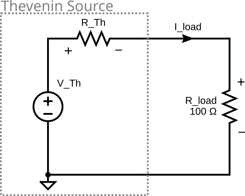
thevenin circuit
Connect the circuit above using the following on the breadboard:
Use the USB power supply and breakout board as the Thevenin equivalent DC voltage source as it should be close enough. Before connecting the R_load resistor to the circuit measure the Thevenin voltage source using the DMM as a voltmeter and record the measurement on the results sheet.
You can just use a single 470Ω as the thevenin resistor (R_Th) as it should fall within the tolerance of the desired resistance. Before placing the resistor in the circuit measure it using the DMM as an ohmmeter and record the measurement in the appropriate place in the results sheet.
Use the same R_load resistors you used in the test circuit. Start by using a 100Ω resistor for the value of R_load. Switch the R_load resistor when required. Make sure to use a jumper wire to connect R_Th to R_load so it can be replaced with an ammeter when required.
Your circuit should now look something like this:

breadboard thevenin circuit
Change the load resistor (R_load) the same way you did for The Test Circuit to different values one at a time (R_load = 100Ω, 220Ω, 470Ω and 1.0kΩ). First measure the voltage across (V_load) the load resistor (R_load) for each load resistor. Then measure the current through (I_load) the load resistor for each load resistor. Be sure to record all of your measurements in the appropriate place on the results sheet.
- To measure the current (I_load) you can replace the yellow jumper wire with the DMM as a DC milliammeter. Make sure you obtain the correct polarity.
If you are satisfied with the results you have for this section, you can now disconnect this entire breadboard circuit as you will not need it anymore.
2.4.3 Norton Circuit
Norton’s Theorem
Norton Theorem states that any linear electrical network as seen from 2 nodes can be simplified to an equivalent circuit with just a single current source (INORTON) and parallel resistance (RNORTON) connected to the load.
To demonstrate that the Norton equivalent circuit behaves the same as both the Thevenin Circuit and The Test Circuit as seen from R_load, connect the circuit below using the equivalent parameters you found in your tests from the previous section.
Click here to see a simulation demo of this circuit.
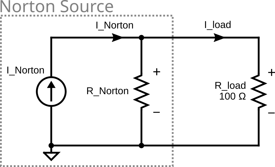
norton circuit
First connect and test the current source by connecting the following on the breadboard:
The LT3092 current source.
A 10kΩ in series with a 680Ω resistor as Rset at pin 1 (Set) of the device
A 10Ω resistor as Rout at pin 2 (Out) of the device, the other ends of both Rset and Rout need to get connected together.
Pin 3 (IN) of the device needs to get connected to the 5V of the USB breakout board.
Connect the red probe of the DMM configured as a DC milliammeter to the Iout point in the diagram above. Connect the black probe to the Gnd pin of the USB breakout board.
Your circuit should look something like this when completed.
.fritz.svg)
current source circuit
Making sure that the circuit is Powered by the USB power supply. Verify that current source is working and is outputting the approximate value required for the Norton circuit by using the DMM as a DC milliammeter. Record this value in the appropriate place on the results sheet.
Now that your current source is setup and working continue by connecting the rest of the circuit:
You can just use a single 470Ω as the norton resistor (R_Norton) as it should fall within the tolerance of the desired resistance. Before placing the resistor in the circuit measure it using the DMM as an ohmmeter and record the measurement in the appropriate place in the results sheet.
Use the same R_load resistors you used in the thevenin and test circuits. Start by using a 100Ω resistor for the value of R_load. Switch the R_load resistor when required. Make sure to use a jumper wire to connect R_Norton to R_load so it can be replaced with an ammeter when required.
Your circuit should look something like this when completed.

norton circuit
Change the load resistor (R_load) the same way you did for The Test Circuit to different values one at a time (R_load = 100Ω, 220Ω, 470Ω and 1.0kΩ). First measure the voltage across (V_load) the load resistor (R_load) for each load resistor. Then measure the current through (I_load) the load resistor for each load resistor. Be sure to record all of your measurements in the appropriate place on the results sheet.
- To measure the current (I_load) you can replace the orange jumper wire with the DMM as a DC milliammeter. Make sure you obtain the correct polarity.
If you are satisfied with the results you have for this section, you can now disconnect this entire breadboard circuit as you will not need it anymore.
2.4.4 Thevenin-Norton Equivalency
Source Transformations
Performing a source transformation consists of using Ohm’s law to take an existing voltage source in series with a resistance, and replacing it with a current source in parallel with the same resistance, or vice versa. The transformed sources are considered identical and can be substituted for one another in a circuit.
Norton \(\rightarrow\) Thevenin conversion \[V_{th} = I_{norton} \times R_{norton}\] \[R_{th} = R_{norton}\]
Thevenin \(\rightarrow\) Norton conversion \[I_{norton} = \frac{V_{th}}{R_{th}}\] \[R_{norton} = R_{th}\]
2.5 Maximum Power Transfer
Maximum Power Transfer
The Maximum Power Transfer Theorem states that the maximum amount of power will be dissipated by a load resistance if it is equal to the Thevenin or Norton resistance of the network supplying power. The Maximum Power Transfer Theorem does not satisfy the goal of maximum efficiency.
2.6 Cleanup
Congratulations, you have completed the experimental part of the laboratory. Before cleaning up, I’d suggest going through your results to check that you have completed everything and that your results make sense. If you find any issues, I’d suggest resolving or making a note of it now. If you are not continuing to work with the equipment please disconnect everything and put it away to prevent it from getting damaged.
3 Post Lab
The following is what you are expected to complete and submit for grading for Lab 2 before the deadline.
The completed Lab 2 - Results sheet template provided at the beginning of this lab manual under Equipment required. This sheet should include the following:
- Your name, student ID and CCID.
- All of the required measurements from the lab procedures.
- All of the required calculations as discussed below.
- The required plots as discussed below.
The Lab 2 - Results sheet needs to be submitted to the Submit (Lab 2 - Results) link on eClass as a pdf document .
Complete the online Quiz (Lab 2 - Post Lab) on eClass.
3.1 Calculations
For these calculation you only need to provide the answers in the space provided on your results sheet, you do not need to show your work.
For the Delta-Wye Transformations under Wye use the Delta-Wye transformation equations to calculate the equivalent Wye values for R1, R2 and R3 from the measured Delta resistance values Ra, Rb and Rc.
From your calculated values of R1, R2 and R3 from the previous step, calculate what the resistance between the terminals labelled u-v, v-w and w-u should be.
For the Delta-Wye Transformations under Delta use the Wye-Delta Transformation equations to calculate the equivalent Delta values for Ra, Rb and Rc from the measured Wye resistance values R1, R2 and R3.
From your calculated values of Ra, Rb and Rc from the previous step, calculate what the resistance between the terminals labelled x-y, y-z and z-x should be.
For Superposition complete the Superposition (V1 Acting Alone + I2 Acting Alone) by summing the values of each cell in the V1 Acting Alone table with the corresponding cell in the I2 Acting Alone table.
For the Thevenin Circuit calculate the power supplied by the voltage source (P_source) and the power dissipated by the load (P_load) for each value of R_load. Then calculate the overall efficiency of the circuit.
For the Norton Circuit calculate the power supplied by the current source (P_source) and the power dissipated by the load (P_load) for each value of R_load. Then calculate the overall efficiency of the circuit.
3.2 Plots
To create your plots you can use whichever software you would like (Excel, Matlab, etc), export your plot as an image and import it into your Lab 2 - Results sheet in the appropriate place.
Your plots should include:
- A Plot title
- Label your axes and show what unit of measure is used.
- Include a marking for your datapoints.
- Include a line between your datapoints in the same series.
- Include a legend.
- Make sure your scales are appropriate and visible.
Characteristic Plot: For each of these 3 circuits: The Test Circuit, Thevenin Circuit and Norton Circuit plot the load current vs. load voltage on the same plot.
Thevenin Circuit Plot: Plot the load power vs. load resistance as one series and the circuit efficiency vs. load resistance as a second series using a secondary y-axis scale.
Norton Circuit Plot: Plot the load power vs. load resistance as one series and the circuit efficiency vs. load resistance as a second series using a secondary y-axis scale.
3.3 Questions
Complete the online Quiz (Lab 2 - Post Lab) on eClass.