Parallel Data Transfer
By
Michael Cumming
A simple solution to projects requiring relatively short range (up to 200m), data transmission in serial or parallel modes is the use of the kits supplied by Ramsey Electronics. The two devices I have tested are the TxE-433 4 bit parallel data transmitter module and the RxD-433 4 bit parallel receiver module. Each device performed well and cost under $30. Although they are called kits, the devices are surface mount PC boards that are assembled, soldered, drilled and only require that leads be soldered into the VCC, GND, and data connection holes. The only sugnificant problem with the kits is the limited documentation that accompanies the circuit. The documentation below has been developed to supliment this and should clear up some of the confusing issues in getting started.
The kits are available at http://www.ramseyelectronics.com/hk/hobbykits.htm. Within Edmonton orders can be made through Alfa & Central Communication located near 77th avenue and 85th street. Their web site is at http://www.connect.ab.ca/~alfa/.
Using the Transmitter and Receiver Pair
Data Addressing
The transmitter has the ability
to address more than one receiver. The address contacts on the transmitter
are labeled A0->A7 and are used to encode the 4 bits of data into a form
that can be decoded only by receivers that are set to the same address.
To set the address lines, individual lines are connected to ground and
the remaining lines are left open. This is the same on both the transmitter
and receiver. Information of the encoder chip used in the transmitter
circuit can be found at the link http://www.holtek.com.tw/docum/Consumer/2_12e.htm.
Information on the decoder chip used in the receiver chip can be found
at the link http://www.holtek.com.tw/docum/Consumer/2_12d.htm.
Sending Data
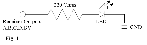
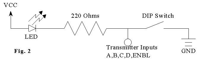
The transmitter and receiver are very easy to impliment and a test circuit can be built by simply connecting each of the receiver outputs to an LED circuit as in Fig.1 and connecting the transmitter inputs to a switch/LED circuit as in Fig. 2.
On the transmitter, the data lines and enable line work like the addressing lines. The value of the line is concidered one unless the line is tied to ground. Interfacing is simple, because both the encoder and decoder chips contain internal pull-up resistors on all the input lines. The values placed on the 8 bit address lines and the 4 bit data lines are encoded in the transmitter and sent out at a frequency of 433MHz. The receiver decodes all values it are sent by any transmitter and determines if the address bits of the recieved value match the settings on its own address lines. Any RxE-433 receiver with the same address line configuration will place the data on its internal latch and output it on its data lines (A,B,C,D). Data is sent on the transmitter by setting its data lines (A,B,C,D) to Vcc or GND and then tying the enable line (ENBL) to GND for a short time. While the enable line is low the transmitter is opperating and any value on the data lines is being transmitted, so even if the value changes, this change will be reflected at the reciever. The valid data line (VD) on the receiver is set high when a correctly addressed value is decoded. The valid data line continues to be high as long as its counter part transmitter enable line is set to GND. At this time, I have not had the oportunity to attach an ocsilloscope to the valid data output so though my current tests suggest that the valid line is held high constantly, it may be the case that the valid line is pulsing at some frequency rather then constant. Some inconsistant data was received on rare occations when the system was connected to our project an a pulsing valid line could be the cause.
Power Connections and Antenna
The voltage input suggested by Ramsey for the receiver and transmitter is 5V. This is because the result is that the outputs will have a high value of 5V which will allow easy interfacing with other CMOS inputs. The Vcc voltage of the receiver and transmitter can be raised for better reception and this possibility is eluded to in the supplied documents but it is also suggested that this might not be health for the circuit if a bandwidth on the receiver is set to a value other than 4800 Hz. It is probably advisable to set the Vcc for both circuits to 5V. The test circuits I have worked with work well with a Vcc of 5V and there is no need of extra interfacing circuitry.
The antenna tested was simply a 6.5 inch peice of wire, directly soldered to the ANT connection drillhole. I was able to sucessfully transmit within a building up to about 200ft across several room. A more powerful antenna tuned to 433 MHz would substantually increase the range of reception. This would be much more obvious if line of sight is maintained outdoors rather then in a closed building.
Bandwidth Control
Bandwidth control is achieved with the connection
of jumpers on the receiver. Frequency bandwidths of 600 Hz, 1200
Hz, 2400 Hz, and 4800 Hz are available but in experiments only the 4800
Hz value worked consistantly under varied conditions. When operation
required that communications be conducted inside a building, the 4800 Hz
with was the only that worked. The use of narrower bandwidths are
suggested by the documentation for longer range communication and probably
is the case when line of sight can be maintained but if data rates and
accuracy of transmitted data are required within enclosed structures then
the jumpers should be set to the maximum value of 4800 Hz.
Limitations
A limitation of the design of the devices is the
size of the drill holes. The size of the holes drilled for the address
lines, data lines and others are too small for standard 20 gauge wire.
As a result I had to use ribbon cable instead. It is important not
to make any mistakes while soldering because the devices are surfacemount
and repairing mistakes is extremely difficult. For best results,
split the ribbon cable for about 2cm at the end then strip the insulation
from 1cm of the end of the wire. For each wire twist the strands
and then hold them in a vice. Solder the length of the exposed wire
to make it solid then clip the very end of the wire to romove any bumps.
Fit the wires into the hole and solder them in. If possible an attempt
to drill out at least the antenna hole of the receiver to accept a 20 gauge
wire is advised. It is very suseptible to breaking off because it
has no support.