| The Altera UP1 boards come equipped with a PS2 mouse connector. The final project that our group did incorporated a mouse using the PS2 port of the UP1 board. A true PS2 mouse was not provided in the lab, however we were still able to obtain data from the mouse. The data obtained had a format similar to that of a true PS2 mouse. This application note describes how data was captured from the mouse. Also provided with this application note is VHDL code that displays a mouse cursor and current mouse data on a VGA monitor. |
Copyright of sorts:
We welcome other 552 groups to use and/or copy our VHDL code and implementation notes. The code was compiled using MAX2PLUS Version 8.1. Compile the VHDL code with the VHDL 93 flag not set.
It is asked that any re-use of the information provided in this application note or in the VHDL code provided be clearly referenced at the top of any file in which material from this application note is used.
We ask for this acknowledgement due to the fact that the interpretation, interfacing, and testing of the mouse encompassed 1/3 of the total development time of our project. The implementation of the mouse in our code was not overly difficult however, as explained below, problems were encountered in obtaining data from the provided mouse which became quite time consuming. Also, included in the VHDL code for this application note, another 1/3 of our project is disclosed in the code we use for video signal generation (Even though the general method for signal generation is not our own)
We would be interested in hearing from and possibly co-developing a mouse interface with another group for a true PS2 mouse (see explanation below).
Our references for the mouse:
Altera: PS2 mouse data packets and board pinouts.
| User will include the following notice with any copies it makes of the Copyrighted Materials, including any technical or educational publications that incorporate any portion of the Copyrighted Materials: "Altera is a trademark and service mark of Altera Corporation in the United States and other countries. Altera products are the intellectual property of Altera Corporation and are protected by copyright laws and one or more U.S. and foreign patents and patent applications." |
General PS2 information & code examples http://www.insightsystems.com/gatech/ps2keyboard.html
| These web pages and projects were created by Georgia Tech
students Doug McAlister, Gauthier Philippart, and
Michael Sugg. |
Logitech: General technical information from Application note 1410 ftp://ftp.logitech.com/pub/TechSupport/MOUSE/HELP/1410.txt
Our references for video generation:
http://www.ece.gatech.edu/users/hamblen/ALTERA/mips.zip
PS2 background information:
The pinout of a true PS2 mouse is shown in Figure 1. Notice that 2 views are provided. The figure on the left refers to the pinouts of the mouse cord when you are looking to the plug (cord facing away from you). The figure on the left shows the port on the Altera UP1 board with the jack facing towards you. Table 1 describes the what the pins of a PS2 mouse are for.
| Pin | Function |
| 6 | No connection |
| 5 | Clock |
| 4 | Vcc |
| 3 | Ground |
| 2 | No connection |
| 1 | Data |
It should be noted that the PS2 port on the Altera UP1 board is not limited to use by a mouse. Another common PS2 device is a keyboard. The pinouts for both a keyboard and mouse are the same.
The PS2 communications protocol provides a method of connecting peripherals to a 2 wire clocked serial interface. When both the clock and data lines are high, either the peripheral or the host can initiate a data transfer. Typically the data and clock lines are pulled high in the peripheral. Open collector devices are then used to force the clock and data signals low.
The entity transmitting data onto the PS2 port must provide the clock for the data transfer. For example, when the mouse is moved, it will want to report its new condition to the host. To do this, the mouse will assert the data line appropriately, and provide a clock on the clock line. If the host wanted to send information to the mouse, the host must provide the clock.
Mouse used in lab:
In the lab a Starmouse mouse was used. It was purchased from Compusmart for $15.00.
Before any attempt was made to capture data from the UP1 board, the
mouse provided in the lab was connected to an oscilloscope.
This was done to ensure that data produced by the mouse corresponded with
the data packet format given in the UP1 manual for a PS2 mouse. The
mouse did not operate according to the specifications given in the Altera
documentation.
(see http://www.ee.ualberta.ca/~elliott/ee552/AlteraDoc/up1_board_documentation.pdf
pages 13, 27)
To ensure that we were not interpreting the UP1 manual incorrectly, Mr. Kees connected the mouse to one of the HP workstations on the 5th floor. When the mouse was connected to the HP workstation, the workstation would not boot. To further verify that something was different about the mouse, we configured a Windows95 based machine with a generic PS2 mouse driver. A different brand of PS2 mouse would operate correctly with the generic driver, but the mouse provided in the lab would not operate at all.
After further research, the design group found that true PS2 mice only have a 4 wire interface. The provided mouse has a 6 wire interface. Also, a true PS2 mouse should only have 2 buttons. The provided mouse has 3 buttons. With this information, it was decided that we were not dealing with a true PS2 mouse. One possible explanation is that the provided mouse is a PS2/serial hybrid, such as those produced by Logitech. A hybrid mouse is capable of being used on either a PS2 or serial port depending on the driver used.
Another explanation is that, like a PS2 keyboard, the mouse must be initialized by the host before it can operate correctly. No information could be found to suggest this is true, but it is a possibility none the less. One suggestion from a classmate was to locate the code to a Linux driver for a PS2 mouse to see if an initialization string could be found. This was attempted, however, due to severely limited time constraints, a PS2 mouse driver was not located.
Getting closer to data from the mouse:
After a period of experimentation, it was discovered that the provided mouse displayed similar characteristics to both serial and PS2 mice.
Example #1. A PS2 mouse will provide its own clock when the mouse would like to send data to the host. The mouse in the lab would provide its own clock only when the data line (Pin 1) was connected to ground. This connection of the data line to ground produced a well formed clock signal from the mouse. However, the data packets produced by the mouse in this configuration were rather boring, being all 0's.
Example #2. To further complicate matters, the mouse in the lab would only reliably produce data packets when the clock line was connected to Vcc. The data produced by the mouse with the clock line held high appeared to have 3 data packets per transmission. (To get a single packet for examination purposes, take the ball out of the mouse and hold one of the mouse buttons down to get 1 data packet; release the button to get another data packet.)
Since the mouse would not provide both the clock and a data packet using a single wiring configuration, the design team devised a method of capturing the data produced by the mouse without a mouse generated clock.
With the mouse wired to produce a clock , the period of the clock produced by the mouse was recorded to be 800us. The mouse was then permanently configured to produce only data packets (Pin 6 connected to Vcc). This connection was done internally to the mouse so that we were able to plug the mouse into the PS2 port of the Altera UP1 board.
Clocking & data packet formats:
It was determined that the first and last data bit of all mouse transmissions were the same regardless of what was being done to the mouse. The first bit was termed the start bit. The start bit is recognized by a high to low transition of the data line. (The data line of a PS2 mouse is held high when no data transmission is taking place.
Using the clocking information previously obtained from the mouse, it was discovered that there were 29 bits in each data transmission sent by the mouse.
At this point it was decided to invert all incoming data. The data produced by the inversion was more intuitive in the sense that when a button was pushed, the state of the bit representing the button was logic 1, not logic 0.
Data from the mouse is captured by looking for the start bit. Once the start bit has arrived, the software will wait for 400us, and then latch the first bit (the start bit) from the mouse. Each bit following the start bit is then captured at 800us intervals until all 29 bits are received. This method of capturing data from the mouse reads the state of each bit at the "center" of each bit pulse.
Yes, we did notice that there are only 6 bits provided by the mouse to describe the rate of motion of the mouse in the Y direction while the mouse describes the rate motion in the X direction using 7 bits. We postulated that fewer bits are used for the description of motion in the Y direction due to the fact that most monitors have more pixels in the x direction than in the Y direction. Thus, a higher sensitivity is required to smoothly describe motion in the X direction.
After extensive testing, the 29 bit data transmission was determined to have the format shown in Figure 2:

Some bits in the data transmission produced by the mouse are constant, others vary depending on how the mouse is being moved. The data transmissions produced by the mouse are similar to that of a true PS2 mouse, but not identical.
Description of motion:
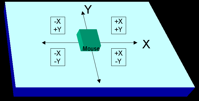
The mouse appears to use a right handed 2 dimensional Cartesian coordinate system. For example, when looking down on the mouse with the cord of the mouse pointing towards your body, movement to the right is positive; movement to the left is negative. Movement away from your body is positive, movement towards your body is negative. See Figure 3 for a graphical representation of this concept.
Movement in the X direction:
Movement in the X direction is characterized by bits 1, 2 and bits 11 to 17.
The X direction bit and the X overflow bit will be at the same same logic state if an overflow has not occurred. If an overflow occurs the X direction bit and the X overflow bit will differ. The magnitude of the rate of change of position of the mouse is given by bits 11 to 17.
The number represented by bits [11..17] is in two's complement format. If the direction bit is set, movement is in the negative direction. Bits [11..17] must be inverted and a 1 added to produce the magnitude of the rate of change in the X direction.
If the direction bit is not set, the number represented in bits [11..17] can be used as is with no further modification.
Movement in the Y direction:
Movement in the Y direction is described by the mouse using the same format as movement in the X direction. The only difference is that 6 bits (bits [22..27]) are used to describe the rate of motion instead of the 7 bits used to describe motion in the X direction.
Mouse buttons:
True PS2 mice only have 2 buttons. The mouse provided in the lab has 3 buttons. A data bit representing the state of the third button was not found.
The right and left mouse buttons do have data bits associated with them. Bit 5 corresponds to the state of the right mouse button. Bit 6 corresponds to the state of the left mouse button. When either of the buttons are pressed the state of the corresponding bit is set. When the button is released, the value of the corresponding bit is then reset to logic 0.
VHDL test code:
The following test code was developed by our design group to show the content of data transmissions from the mouse. Also included in the following test code is a mouse pointer. The movement of the mouse may seem "jittery" as we snap to a rather large grid. A large grid was used to help simplify the code. The video generation method used in the code is referenced in tcgrom.mif.
These 3 files are required to run the demonstration: mouse.vhd mouse.acf tcgrom.mif
The purpose of this application note is not to describe the graphics routines used, but to describe the implementation of the mouse with the UP1 board. As such, the video routines will not be discussed further in this application note.
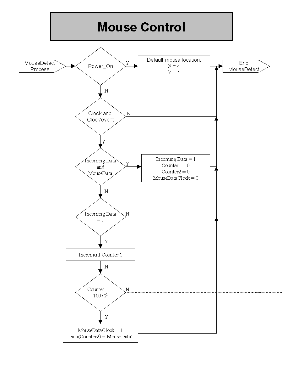
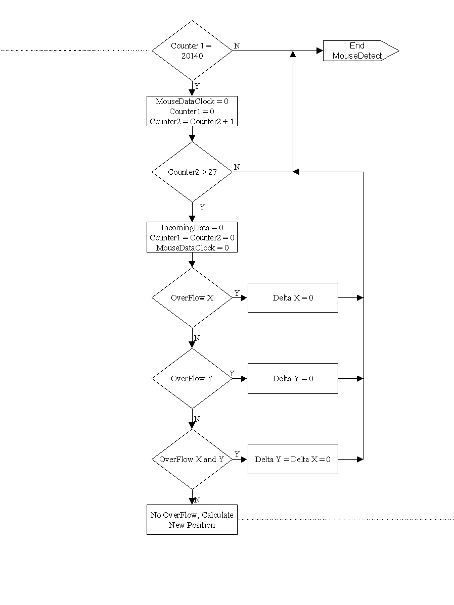
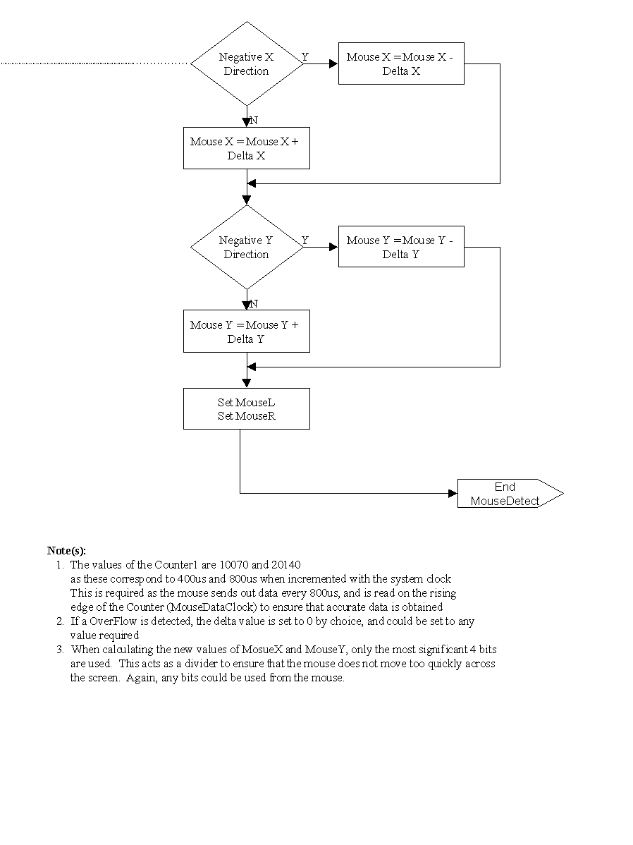
The following flowcharts attempt to reveal the algorithms used to capture data transmissions from the mouse, and the algorithms used to calculate the X and Y position of the mouse cursor on the screen. It is exceptionally difficult to describe such a simple, but long algorithm. Please review both the flowcharts and the VHDL code side-by-side. Using both should allow for a better understanding of the algorithms used. If there are any questions please contact amcdermo@gpu.srv.ualberta.ca and I, or one of my team will attempt to help you.