This page outlines the complete design for Field Programmable Gate Array (FPGA) controlled robot that exhibits light following, sound sensing, and object detecting abilities. The robot uses an Actel 1020B FPGA to control all of its logic behaviour while external analog circuitry provides the sensory inputs to the FPGA. The purpose of this design is to demonstrate how an FPGA can be effectively used to control a robot.
The FPGA design was developed under VHDL using a behavioural type description of the desired state machine process. Actel software was used to transfer the VHDL design to a fuse-map suitable for the Actel FPGA.
The external circuitry feeding the FPGA was designed as to provide logical high or low inputs that the FPGA could interpret in response to its external environment. The bump sensor, table edge sensor, both light sensors, and the sound sensor all send a high signal to the FPGA when any of them are triggered. The sound sensor and light sensors have on/off switches to allow for different modes of operation and to allow for operation of the robot in environments where these sensors may be too sensitive.
One SGS-Thomson dual H-bridge was used to drive the motors on the robot and a pulse width modulation (PWM) scheme is used to control the speed of the motors through them. The H-bridge provides a simple logic controlled interface between the FPGA and the motors.
The robot, built from the chassis of a toy radio-controlled car, contains two motors, each driving one rear wheel (total of four wheels). Initially, the each front and rear wheel pair was connected using a rubber "tank" track. Due to the excessive friction this caused, the tracks were later removed. Steering is "differentially" controlled, as opposed to every day steering seen on cars or trucks. Differential, or "tank", steering is much simpler to control since the easiest method of turning requires turning on motor on and the other off.
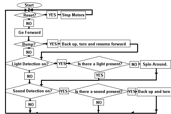
The robot is designed to operate independent of any human control but still be able to interact with its environment: a light-coloured table-top. Its independance is achieved through its table edge and bump sensors, mounted on the front of the vehicle using aluminium sheeting. The two bump sensors, fashioned from momentary push-button switches, are mounted facing forward. The table edge sensor is a Hamamatsu photoreflector facing downwards, about three milimeters from the table-top. When either of these sensors are activated, the robot will stop, back up, and then turn left and proceed. This allows the robot to protect itself from and navigate around life-threatening table edges and annoying objects.
The ability to interact with humans is provided through the light sensors and the sound sensor. The first light sensor is another photoreflector mounted on the top of the robot. Whenever an object or a strong infra-red energy source passes over the photoreflector, a signal is sent to the FPGA and the robots turns as it did when it encountered a bump signal. This allows the robot to play tag with people.
The second light sensor is a photocell mounted facing forward on the robot. This sensor is designed to give the robot light following ability. When the robot is operating (selected by the user using a toggle switch) in this mode it will spin about its center until a light source is detected by the photocell which will then cause it to drive forward towards the light source. If the light source is lost the robot will begin to spin again until it finds it again.
The sound sensor is a microphone mounted on top of the
robot. High intensity sounds, such as a loud clap (or really loud
music) will alter the direction of travel of the robot and cause the robot
to back up, turn and continue.
The design for the robots behaviour was implemented by the following state machine diagram:
Normal Operation:
back to the top
A behavioural description of this state machine was developed under VHDL and can be seen below at the bottom of this
document. This description provided the control logic for the the
robot. A separate VHDL entity was created to interpret the logic
behaviour and to control the motor behaviour. The SGS-Thomson H-bridges required four inputs from the
FPGA- left, right, left pulse, and right pulse. The left and right
signals controlled the direction of each motor, with 'high' being forward
and low being reverse. The left pulse and right pulse is the pulse width modulated (PWM) input for the
motors. This allows control of motor speed by varying the width of
the output pulse. For this design the duty cycle of the PWM was set
at 50 %. A smaller duty cycle (ie. in one cycle the "high", or on, part
is shorter than the "low", or off, part) will result in a slower motor; a
larger duty cycle (it's on longer than it's off) will result in a faster
motor.
A counter was also created to set the time for the robot to back up, turn and then continue forward. When the turn sequence was initiated, the robot began backing up. When the counter reached the halfway mark, the robot began to turn until the full time was reached. The code was written such that no external stimulus could interrupt the turn sequence until it was completed. In addition, the count for the back up and turn was set to 2500 clock cycles, since we wanted the robot to back up for ½ second and then turn for ½ second respectively (given a 2500 Hz clock signal).
The clock signal was set at 2.5 kHz primarily due to the fact that the maximum clock frequency for the H bridges was 5 kHz. This allowed a wide margin for us to work with and was still fast enough for the robot to handle any inputs from its environment. Given that the clock signal was so low, extremely precise clocking wasnt necessary. Therefore, we chose to implement the clock with an astable multivibrator using a 555 Timer (Section 8-8 of the ARRL Handbook) The clock circuit can be seen below with the Schematics.
A motor speed feedback control scheme was initially planned for the design but couldnt be implemented due to it being too large for the Actel chip. (An attempt to modify the VHDL code to reduce the size didnt reduce the size nearly enough for the design to fit on the Actel chip.) This scheme used the FPGA to measure the speed of the wheels by counting the output of shaft encoders mounted on the wheels. The shaft encoders were to be implemented with Hamamatsu photoreflectors (P5587 -- the same ones used in the first light detector and table-edge detector) and a segmented disk, resembling a black and white pie-chart, attached to each rear wheel. The alternating black and white stripes cause the output of the photoreflector to pulse and these pulses were to be counted by the FPGA. The FPGA would then compare a sample count to a desired count and adjust the pulse width duty cycle accordingly. Two high a count would indicate that the motor was spinning too fast, thus requiring the PWM duty cycle to be lowered, and vice-versa. The code for this was created and simulated and can be seen below under the motorcontrol entity.
The FPGA was tested using Qhsim to simulate the VHDL design and using the complete final design to test its response to its various inputs. The Qhsim results from a back annotated simulation indicated the design operated as intended and was ready to implement on the FPGA. Simulation results can be viewed from these files:
While the VHDL coding was being done, work began on the hardware for the robot. This simultaneous work was essential as we had to ensure that any unexpected hardware behaviours or glitches could be handled by the final FPGA design; thus the hardware had to be complete before the FPGA fuses were blown.
Once the FPGA was fuse-mapped, it was connected other hardware and the robot was put through a series of tests to check its operation and the complete operation of all circuitry. Since the external circuitry had been tested and verified, the complete design itself was ideal for use in testing the FPGA. The response of the FPGA to each sensor was tested individually and then the robot was tested under various conditions where one or more stimulus were present.
The only problem observed upon attachement of the FPGA was the amount of feedback from motor voltage dips and spikes. These glitches occured when the motor changed direction and had a tendency to introduce further glitches inside the FPGA logic. A temporary solution was implemented by carefully adjusting the dual power supplies (one to the logic and one to the motor). Although not ideal, this solved the glitch problem enough to test the complete design.
A better solution (which will be implemented during the Christmas
break) is to set up opto-coupled isolation between the motor and it's
power source from the control logic and it's power source. Please see our
Cad Tool submission for further details.
The final robot design operated as intended and simulated. A larger FPGA would have allowed the complete design to be implemented with the feedback control loop. Implementing an FPGA in this design greatly reduced the amount of circuitry needed and provides the option of changing the control behaviour by changing the FPGA. This project demonstrated the flexibility of FPGAs, allowing us to have the FPGA interact with the real world using many simple components.
We would also like to mention that, although flexible, the Actel 1020B is relatively limited in size, thus limiting the complexity of our project. Due to the modular nature of our project, we were able to scale it down once the reality of the limitations of the device hit us -- about three weeks before the end of the semester.
We recommend to all future EE 552 students that they design a project
with a core state machine containing only 10 to 20 states (see our flow chart above) in addition to a few
limited parallel processes (like
our
pulse-width modulation motor control).
Components:
The following is a list of components required for the project:
1 Actel 1020B FPGA- 44 Pin PLCC -- Logic for controller
1 SGS-Thomson L293D dual H-bridge IC -- Pulse
control for motors
2 Hamamatsu P5587 Photoreflectors -- table edge sensor,
and tag sensor
1 chassis -- Body of vehicle
2 electric motors -- Drive for the vehicle
1 photocell array -- Light-sensing capability
1 microphone -- Sound-sensing capability
1 LM386 op-amp -- Amplification of sound for
microphone
2 LM311 comparators -- To ensure a proper high/low
signal to interface light and sound sensor to TTL levels.
2 bump switches (2 pole) -- Table edge and table-top
object detection
4 two-pole switches -- Function toggling for
debugging of sensors.
1 555 Timer
-- For clock signal.
assorted resistors and capacitors, inverters.
Note: We have made all of the Hamamatsu catalogues available
to Morris Locker in the EE Stores room. They specialize in light
sources and sensors. The SGS-Thomson dual H-bridge is also now available
through the EE Stores or through Active Electronics.
Schematics
and Pin Layouts:
555 Timer:


 .
.
LOGIC.VHD
--high level description of robot behaviour
library ieee;
use ieee.std_logic_1164.all;
entity logic is
port (reset, clock, sound, bump, light, lighton, soundon : in
std_logic;
left,right: out std_logic;
leftpulse,rightpulse: inout std_logic;
motor: inout std_logic_vector(1 downto 0) -- new.
);
end logic;
architecture behaviour of logic is
component motorcontrol
port(reset, clock: in std_logic;
--clock signal
next_state: in std_logic_vector(1 downto
0); --logic for motor
left,right: out std_logic;
--forward/reverse
leftpulse,rightpulse: inout std_logic
--pwm output for each motor
);
end component;
for all: motorcontrol use entity work.motorcontrol(behaviour);
signal motor_internal: std_logic_vector( 1 downto 0);
--signal motor: std_logic_vector(1 downto 0);
BEGIN
comb_logic : PROCESS(sound,soundon,light,lighton,bump)
BEGIN
CASE bump IS
WHEN '0' =>
-- NO BUMP
motor_internal <= "11";
-- move forward
CASE lighton IS
WHEN '0' =>
-- NOT looking for LIGHT (selected by USER)
--motor_internal <= "11";
-- move forward
CASE soundon IS
WHEN '1' =>
-- SEEKING sound (selected by USER)
CASE sound IS
WHEN '1' =>
-- FOUND sound
motor_internal <= "01";
-- turn Counter-clockwise
WHEN OTHERS =>
-- NO sound
motor_internal <= "11";
-- move forward
END CASE; -- END of CASE for SOUND
WHEN OTHERS =>
-- NOT SEEKING sound (selected by USER)
motor_internal <= "11";
-- move forward by default.
END CASE; -- END of CASE for SOUNDON.
WHEN '1' =>
CASE light IS
WHEN '0' =>
-- NO light found.
motor_internal <= "11";
-- move forward
WHEN '1' =>
-- FOUND light
motor_internal <= "10";
-- turn Clockwise (ie. towards the light)
WHEN OTHERS =>
motor_internal <= "11";
-- move forward by default.
END CASE; -- END of CASE for LIGHT.
WHEN OTHERS =>
motor_internal <= "11";
-- move forward by LIGHTON default
END CASE; -- END of CASE for LIGHTON
WHEN OTHERS =>
-- BUMP is ON or UNKNOWN (just to be safe)
motor_internal <= "01";
-- turn Counter-clockwise to AVOID object or edge.
END CASE; -- END of CASE for BUMPON
--
END PROCESS comb_logic;
--
motor_output: PROCESS(reset,clock)
BEGIN
--
IF reset='1' THEN
motor <="11"; -- manual reset
ELSIF rising_edge(clock) THEN
motor <= motor_internal; -- send output to motor
END IF;
--
END PROCESS motor_output;
pm: motorcontrol PORT MAP(reset,clock, motor,left,right,leftpulse,rightpulse);
-- connect to motorcontrol routine
END behaviour;
MOTORCONTROL.VHD
-- motorcontrol: interprets control logic and intitiates motor control
-- and turning subroutines
LIBRARY ieee;
USE ieee.std_logic_1164.ALL;
ENTITY motorcontrol IS
PORT(clock,reset: IN std_logic;
--clock signal and reset
next_state: IN std_logic_vector(1 downto
0);
left,right: OUT std_logic;
--forward/reverse
leftpulse: INOUT std_logic;
rightpulse: INOUT std_logic
--pwm output for each motor
);
END motorcontrol;
ARCHITECTURE behaviour OF motorcontrol IS
BEGIN
logic : PROCESS(clock,next_state,reset) --H bridge forward/reverse
--left right outputs
VARIABLE turncount, turntime,turnon: INTEGER;
VARIABLE motor_input: STD_LOGIC_VECTOR(1
DOWNTO 0);
--turncount-counter to compare to
BEGIN
turntime := 3750; -- on a 2500 Hz clock this
is 1/5 seconds
IF (rising_edge(clock)) THEN
IF (reset='1') THEN
turncount :=0;
turnon:=0;
motor_input := next_state;
left <= '1';
right <= '1';
END IF;
-- when motor_input=00 it drives forward, motor_input=01 it turns left,
motor_input=10 it turns right
-- by default any undefined case, drives forward
-- left and right signals connect to SGS-Thomson Input pins (1=forward,
0 = reverse),
-- the Enable pins on the SGS-Thomson is for the PWM signal
IF (turnon=0) THEN
motor_input:=next_state;
END IF;
IF (motor_input="11" and turnon=0) THEN
left<='1';
right<='1';
motor_input := next_state;
-- AVOID A BUMP OR TABLE EDGE! (OR TURN DUE TO SOUND)
ELSIF ((motor_input ="01") and (turncount < turntime))
THEN
turnon:=1;
IF (turncount < 1875) THEN -- lasts .75
seconds on 2500 Hz Clock
turncount:=turncount+1;
left<='0';
right<='0';
ELSE
turncount:=turncount+1;
left<='0';
right<='1';
END IF;
-- TAG!! YOU'RE IT! ROBOT SHOULD SPIN AROUND WHEN
"TAGGED" BY HUMAN.
ELSIF (motor_input="10") THEN
turnon:=1;
IF (turncount < turntime) THEN
turncount:=turncount+1;
left<='1';
right<='0';
ELSE
turncount :=0;
turnon := 0;
motor_input := next_state;
END IF;
ELSE
turncount:=0;
turnon:=0;
motor_input:=next_state;
--ELSE
-- turncount:=0;
-- turnon:=0;
-- motor_input:=next_state;
--ELSIF (motor_input="10") THEN
-- turnon:=1;
-- IF (turncount < turntime) THEN
-- turncount:=turncount+1;
-- left<='1';
-- right<='0';
-- ELSE
-- turncount :=0;
-- turnon:=0;
-- motor_input := next_state;
-- END IF;
END IF;
END IF;
END process logic;
--Motor
Speed Feedback Control in VHDL:
--
-- this process will count the shaft encoder feedback pulses.
-- another process will sample the result of this process
--
--count_shaft_feedback: PROCESS (reset, rightfeedback, leftfeedback,
reset_shaft_counters)
-- variable countleft, countright: integer;
--BEGIN
-- CASE reset IS
-- WHEN '1' =>
-- countleft := 0;
-- countright := 0;
-- WHEN OTHERS =>
--
-- CASE reset_shaft_counters IS
-- WHEN '1' =>
-- countleft := 0;
-- countright := 0;
-- WHEN OTHERS =>
-- IF (rising_edge(leftfeedback)) THEN
-- countleft := countleft + 1;
-- ELSE
-- countleft := countleft;
-- END IF;
--
-- IF (rising_edge(rightfeedback)) THEN
-- countright := countright +1;
-- ELSE
-- countright := countright;
-- END IF;
--
-- END CASE; -- END CASE for reset_shaft_encoders
--
-- END CASE; -- END CASE for reset
--
-- l_cntoutput <= countleft; -- assign left count
--> passing integer value to another process
-- r_cntoutput <= countright; -- assign right
count --> passing integer value to another process
--
--END PROCESS count_shaft_feedback;
--
-- this process will sample the output of COUNT_SHAFT_FEEDBACK when
appropriate
-- and then reset the count values in count_shaft_feedback so that
new values
-- can be obtained in the next sampling...
--
-- POSSIBLE PROBLEMS: in the sample_time <= 630, leftcount and rightcount
may change as sample_time
-- goes from 626 to
630. When should "reset_shaft_counters" be done?
--
--
--sample_counters: PROCESS (r_cntoutput, l_cntoutput, clock, reset,
reset_shaft_counters)
--
-- variable sample_time: integer;
--
--BEGIN
-- CASE reset IS
-- WHEN '1' =>
-- reset_shaft_counters <= '0';
-- sample_time := 0;
-- WHEN OTHERS =>
-- IF (rising_edge(clock)) THEN
-- IF (sample_time <= 625) THEN
-- sample_time := sample_time + 1; --
INCREMENT the sample time!
-- signal_sample_time <= sample_time;
--
-- reset_shaft_counters <= '0';
--
--
-- ELSE
-- leftcount <= l_cntoutput;
-- rightcount <= r_cntoutput;
-- reset_shaft_counters <= '1'; --
hopefully, this will happen concurrently.
-- sample_time := 0;
-- reset sample_time.
-- *************** ACTMAP
doesn't like the statement for resetting sample_time to 0.
--
because it's being set too many times.
-- END IF;
-- END IF;
-- IT WON'T DO ANYTHING IF THERE IS NO RISING EDGE.
--
-- END CASE;
--END PROCESS sample_counters;
-- *** END of PROCESS count_shaft_feedback **********************************
-- **** NEW PROCESS: compare_counters *******************************
-- *******************************************************************
-- this process will take the results of rightcount and leftcount and
compare them to an optimal number (ref=12)
-- This number corresponds to the number of shaft encoder pulses desired
every 1/4 second, or 625 clock cycles (2500 Hz clock)
--
--compare_counters: PROCESS (rightcount, leftcount, reset, signal_sample_time,
halftimel, halftimer,motor_input)
-- VARIABLE ref: INTEGER;
--
--BEGIN
-- ref:=12;
-- CASE reset IS
-- WHEN '1' =>
-- halftimel <= 25;
-- halftimer <= 25;
-- WHEN others =>
-- null;
-- END CASE;
-- CASE motor_input IS
-- WHEN "00" =>
-- IF ((ref > rightcount) AND (signal_sample_time = 625)) THEN
-- halftimer <= halftimer +1;
--
-- ELSIF ((ref < rightcount) AND (signal_sample_time = 6256))
THEN
-- halftimer <= halftimer -1;
--
-- ELSE
-- halftimer <= halftimer; -- don't change
the value of halftimer!
--
-- END IF;
--
-- IF ((ref > leftcount) AND (signal_sample_time = 625)) THEN
-- halftimel <= halftimel +1;
--
-- ELSIF ((ref < leftcount) AND (signal_sample_time = 625))
THEN
-- halftimel <= halftimel -1;
--
-- ELSE
-- halftimel <= halftimel; -- don't change
the value of halftimel!
--
-- END IF;
-- WHEN others =>
-- null;
-- END CASE; -- END
the reset CASE
-- END PROCESS compare_counters;
--
--left_halftime <= halftimel; -- pass these values on
to the next process, pwm.
--right_halftime <= halftimer;
--
--pwm: PROCESS (clock,reset,left_halftime, right_halftime)
-- sets up pulse width modulation and adjusts to feedback
--
--VARIABLE time : INTEGER;
--
--BEGIN
--
-- IF (rising_edge(clock)) THEN
--
-- CASE reset IS
-- WHEN '1' =>
-- time :=0;
-- leftpulse<='0';
-- rightpulse<='0';
-- WHEN OTHERS =>
--
-- time:=time+1;
-- IF (time >= 50) THEN
-- time:=0;
-- END IF;
--
-- IF (time < left_halftime) THEN --pulse high
-- leftpulse<='1';
-- ELSE
-- leftpulse<='0';
-- END IF;
--
-- IF (time < right_halftime) THEN --pulse high
-- rightpulse<='1';
-- ELSE
-- rightpulse<='0';
-- END IF;
-- END CASE;
-- END IF;
--
-- END PROCESS pwm;
-- *******************************************************
-- New version of PWM PROCESS ****************************
-- does NOT use feedback *********************************
-- *******************************************************
pwm: PROCESS (clock,reset)
-- sets up pulse width modulation. It NO LONGER adjusts to feedback
-- This PWM signal only controls the speed of the motors.
Direction is controlled in the LOGIC process.
-- We have removed the feedback part of our design due to the
~1000 modules the complete design required.
VARIABLE time : INTEGER;
VARIABLE halftime : INTEGER;
-- In our old version, these two variables were signals
from other processes.
BEGIN
halftime := 1; -- yields a 50% duty cycle.
-- right_halftime := 25; -- yields a 50% duty cycle.
IF (rising_edge(clock)) THEN
CASE reset IS
WHEN '1' =>
time :=0;
leftpulse<='0';
rightpulse<='0';
WHEN OTHERS =>
time:=time+1;
IF (time >= 2) THEN
time:=0;
END IF;
IF (time < halftime) THEN -- pulse high
leftpulse<='1';
ELSE
leftpulse<='0'; -- pulse low
END IF;
IF (time < halftime) THEN -- pulse high
rightpulse<='1';
ELSE
rightpulse<='0'; -- pulse low
END IF;
END CASE;
END IF;
END PROCESS pwm;
-- **************************************************************************
-- counter PROCESS **********************************************************
-- **************************************************************************
--
--counter: PROCESS(input)
--BEGIN
-- output <= input +1;
--END PROCESS counter;
--
end behaviour;
back to the top

The Authors: James Smith and Darren Rempel