Binary to BCD Module Design
General Overview
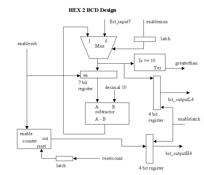
The hardware designed for this section uses the basic binary to BCD algorithm.
The input comes from the function module, which is an ordirary binary value.
This value is input into this module, and two 4 bit output registers hold
the output from the module. One register contains the most significant value,
and the other contains the least significant value for the humidity value
between 0% and 99%.
 Available Documentation:
hex to
BCD module
subtractor to subtract 10
counter for number of times we subtract 10
4 bit register for output
7 bit register for input to mux
VHDL Code for D Flip Flop (latch)
The algorithm

External Circuitry
We connect the 4 bit outputs to LS7447 BCD to 7 segment converters. These then
connect to the common anode displays. We put one resistor of 330 Ohms between
power and the anode. This makes sure that the current entering the TTL chips
is at acceptable levels. This circuit worked fine, except the displays were
somewhat dim, so we just decreased the resistor values.
Signals Used
enablemux - select for mux
enablelatch - enable latch which resets counter
enablesub - enable register to latch, register feeds the subtractor
greaterthan - tells state machine that our least significant value is
still greater than or equal to 10
bit_input7 - the input to the hex2bcd module
bit_outputL4 - the output from the chip with the least significant value of the current
humidity
bit_outputH4 - the output from the chip with the most significant value of the current
humidity
Back to Design Index.
Back to project home page