 Available documentation:
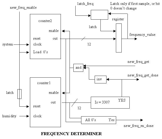
The main idea behind the frequency determiner was to have two counters. Counter2 was the counter which would count the main system clock for a fixed number of counts. Counter1 would count the number of rising edges in the frequency generated by the humidity sensor circuit. Thus, if we start the above two counters at the same time, and always stop both counters when counter2 reaches a certain value, the count from counter1 gives us a relative frequency.
Available documentation:
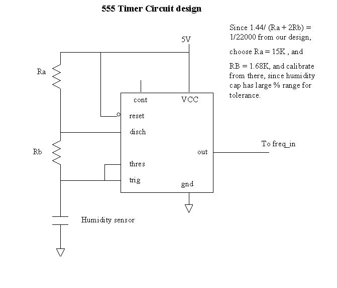
The next calculation determines the range of humidity clock frequencies. The important factor is the range of capacitances of the sensor, being from 112pF (10% humidity) to 140pF (85% humidity). Please see the humidity capacitor specs. The external 555 timer circuit was used because the on-chip RC ocillator did not suit our needs, as our sensor was always below the 1000pF limit in that circuit. We did try using the RC oscillator, but the frequencies obtained were not close to what the calculation showed. The 555 timer circuit worked much better, but we had to make significant adjustments to our 2 resistors in that circuit to get the correct frequency for the capacitance of the sensor. In specific, Ra had to be decreased to under 1K, and Rb was decreased to 11K to obtain the proper frequency. If we had more time, we would have investigated this further. Since we ended up using the 555 timer for the generation of the humidity clock, the frequency f is proportional to 1/C. Thus:
| let f1 = 1/112pF |
| let f2 = 1/140pF |
| f2/f1 = 112/140 = 0.8/1 |
| T2/T1 = 1.25/1 |
| (counter1 counts for 10%) - 0.8*(counter1 counts for 10%) = 75 |
| counter1 counts for 10% = 375 |
Since 375 was chosen for 10% humidity, then 300 counts would occur on counter1 for a humidity of 85%. With our system clock being 3.579MHz, then what is the exact number of counts for the system clock to sample the humidity? Remember, for humidity = 10%, we must have 375 humidity counts on counter1. We chose the frequency of the humidity clock to be 1/(22000*C). So when C = 112pF (10% humidity), then the frequency is 1/(22000*112pF) = 405844Hz. Observe the calculation for the number of counts of the master clock.
| 375*Period(humidity clock at 10%) = counts of master clock * Period(master clock) |
| 375*(1/405844) = counts * (1/3579000) |
| counts = 3307 |
Thus the number of counts that counter2 (the master clock counter) must count per humidity sample is 3307. When counter2 hits this value, we stop counter1 and counter2, and the value in counter1 is the sample of our humidity generated frequency.
There are 2 parts of the design in this portion which may need further explaining. The first one has to do with the the frequency value of the humidity sensor obtained. Imagine if the humidity is at 30.5%. Then, our output may be flopping between 30% and 31%, and our output on the display may not be readable, if it is rapidly switching between the 2 values. Also, since the system clock and humidity clock are not synchronous, then, even though the humidity is constant, the humidity count of counter1 could vary by a maximum of 1 for the constant humidity. This translates into a relative humidity change of 1% in our system as well. So again, the output may flop around between two values (eg. 30% and 31%). To solve this problem, we only record changes of 2%. Since humidity as a value which changes very slowly, a change greater than 2% will never occur between sample periods. This simplifies the design of this feature greatly. All we do is check the least significant bit of the frequency obtained from counter1. If this bit is the same as previously obtained, then we load the new value into the register. Note thus, that we record any even change (0 ,2, 4, 8 ..). This eliminates the changes of 1%, and again, since humidity changes very slowly, only changes of 2%, or 0% will be recorded. Noe also that we must ignore this feature if the sample is the very first one upon reset or powerup. To do this, we have a flip flop to output a 0 upon reset, until the first sample has occured. Then it is set to 1, and remains 1. The signal from this flip flop can be used to load the new frequency no matter what, it its output it 0.
The only other problem that we needed to do some aditional design for, was for counter1, since it is not synchronous with counter2. When counter2 is stopped, we immediately stop counter1, so by the time we latch this sample, then the output of counter1 is stable. As well, the reset to counter1 from the state machine must be an enable signal to a flip flop, so that glitches do not reset our counter1 by mistake.